
How to Use Digital Temperature Sensor Breakout - TMP102: Examples, Pinouts, and Specs

 Design with Digital Temperature Sensor Breakout - TMP102 in Cirkit Designer
Introduction
The TMP102 is a high-accuracy digital temperature sensor that communicates via the I2C interface. It provides precise temperature readings with a resolution of 0.0625°C and operates with low power consumption, making it ideal for battery-powered applications. The TMP102 is commonly used in environmental monitoring, HVAC systems, industrial temperature control, and IoT devices.
Explore Projects Built with Digital Temperature Sensor Breakout - TMP102
 Open Project in Cirkit Designer
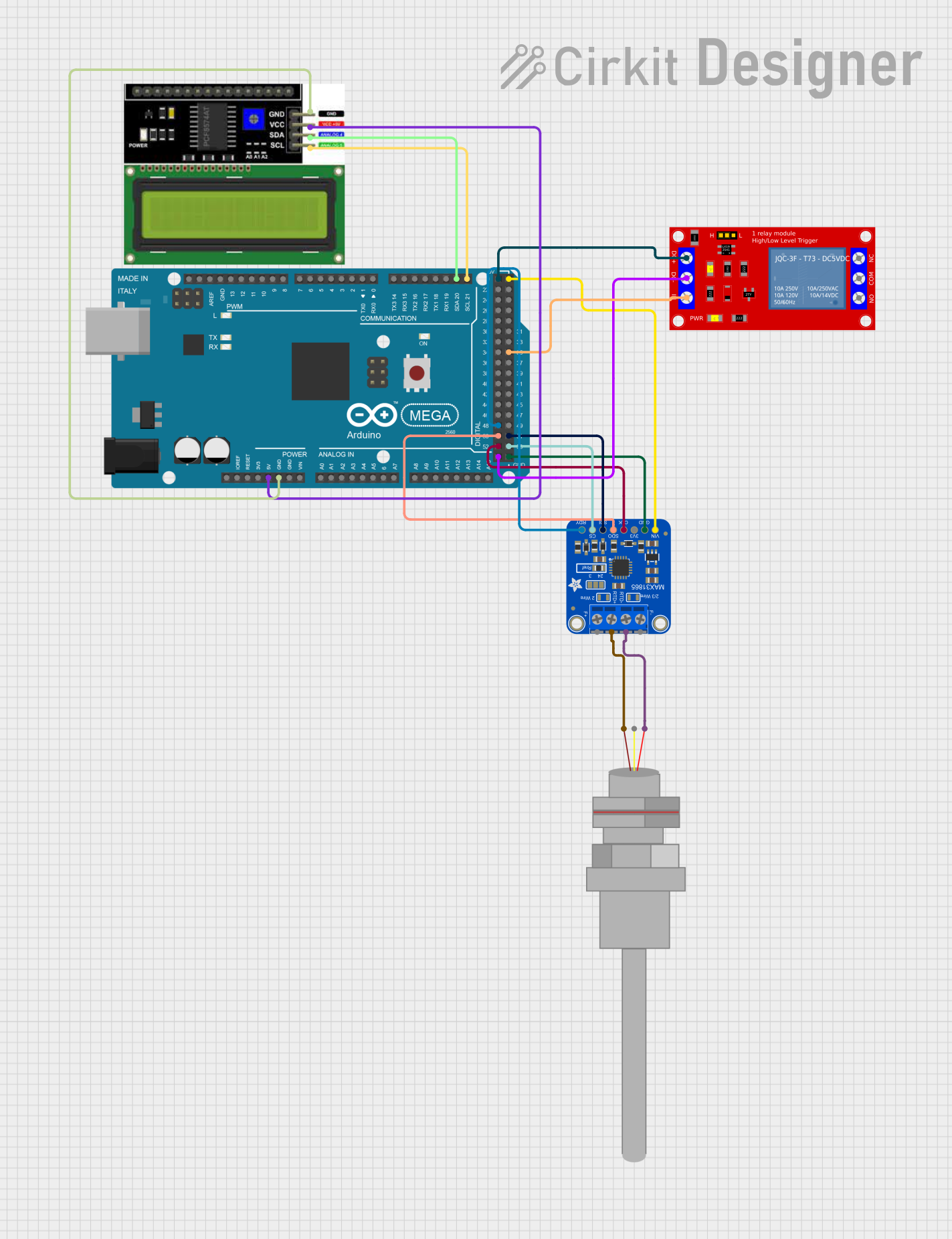 Open Project in Cirkit Designer
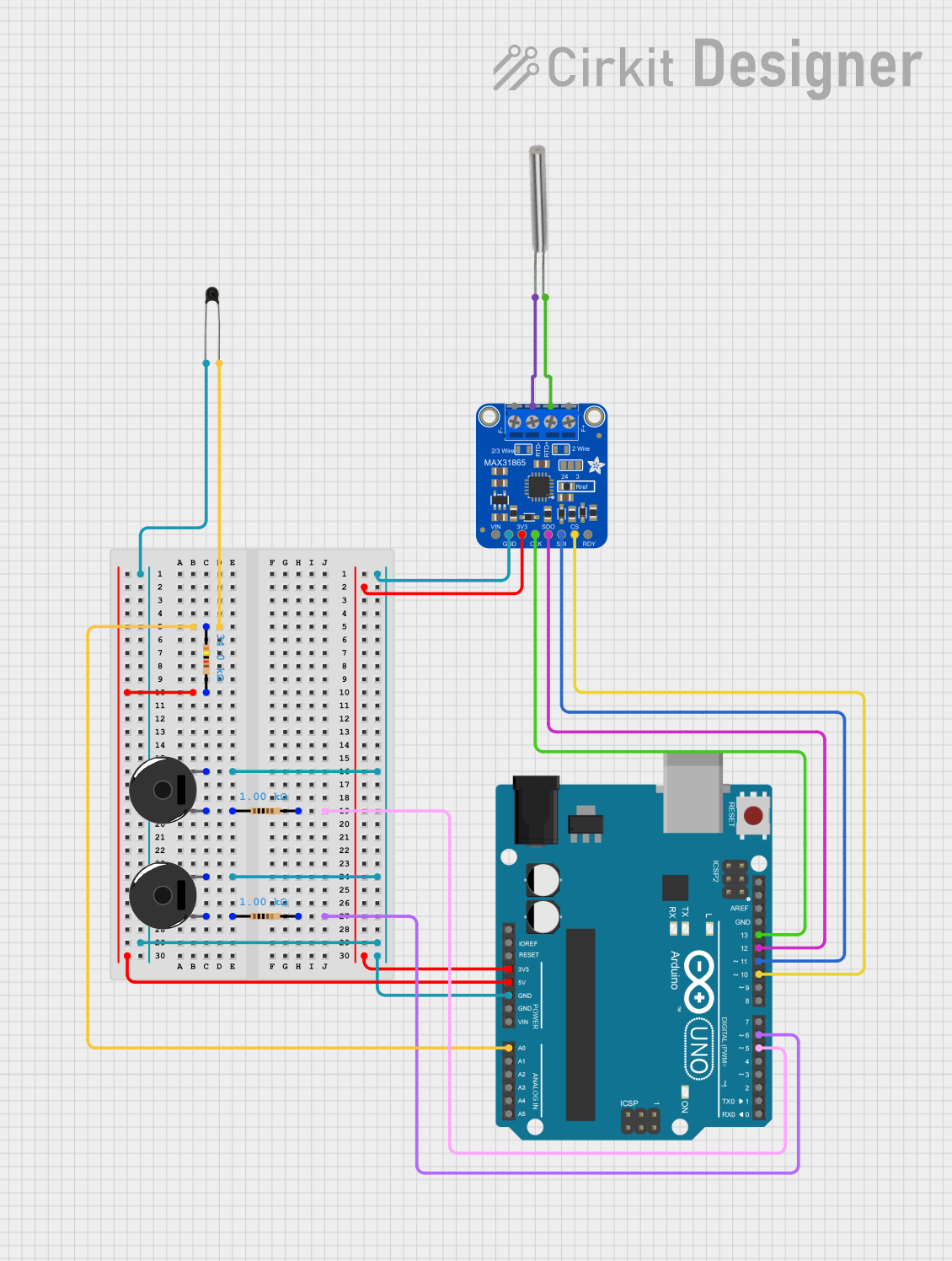 Open Project in Cirkit Designer
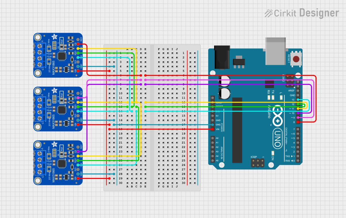 Open Project in Cirkit Designer
Explore Projects Built with Digital Temperature Sensor Breakout - TMP102
Open Project in Cirkit DesignerOpen Project in Cirkit DesignerOpen Project in Cirkit DesignerOpen Project in Cirkit DesignerTechnical Specifications
- Operating Voltage: 1.4V to 3.6V
- Temperature Range: -40°C to +125°C
- Accuracy: ±0.5°C (typical) from -25°C to +85°C
- Resolution: 0.0625°C
- Interface: I2C (7-bit address: 0x48 by default, configurable to 0x49, 0x4A, or 0x4B)
- Power Consumption:
- Active Mode: 10 µA (typical)
- Shutdown Mode: 1 µA (typical)
- Communication Speed: Up to 400 kHz (Fast Mode I2C)
- Dimensions: 0.65" x 0.3" (16.5mm x 7.6mm)
Pin Configuration and Descriptions
| Pin Name | Pin Number | Description |
|---|---|---|
| VCC | 1 | Power supply input (1.4V to 3.6V). |
| GND | 2 | Ground connection. |
| SDA | 3 | I2C data line. |
| SCL | 4 | I2C clock line. |
| ADD0 | 5 | Address pin to configure I2C address. |
| ALERT | 6 | Open-drain output for temperature alert. |
Usage Instructions
Connecting the TMP102 to a Circuit
- Power Supply: Connect the VCC pin to a 3.3V power source (or 1.4V to 3.6V, depending on your system). Connect the GND pin to the ground of your circuit.
- I2C Communication: Connect the SDA and SCL pins to the corresponding I2C data and clock lines of your microcontroller. Use pull-up resistors (typically 4.7kΩ) on both SDA and SCL lines if not already present in your circuit.
- Address Configuration: Use the ADD0 pin to set the I2C address:
- Connect ADD0 to GND for address 0x48 (default).
- Connect ADD0 to VCC for address 0x49.
- Leave ADD0 floating for address 0x4A.
- Connect ADD0 to SDA for address 0x4B.
- Optional Alert Pin: Connect the ALERT pin to a GPIO pin on your microcontroller if you want to use the temperature alert functionality.
Example Code for Arduino UNO
Below is an example of how to use the TMP102 with an Arduino UNO to read temperature data:
#include <Wire.h> // Include the Wire library for I2C communication

#define TMP102_ADDRESS 0x48 // Default I2C address of TMP102

void setup() {
  Wire.begin(); // Initialize I2C communication
  Serial.begin(9600); // Start serial communication for debugging
  Serial.println("TMP102 Temperature Sensor Example");
}

void loop() {
  float temperature = readTemperature(); // Read temperature from TMP102
  Serial.print("Temperature: ");
  Serial.print(temperature);
  Serial.println(" °C");
  delay(1000); // Wait 1 second before reading again
}

float readTemperature() {
  Wire.beginTransmission(TMP102_ADDRESS); // Start communication with TMP102
  Wire.write(0x00); // Point to the temperature register
  Wire.endTransmission();

  Wire.requestFrom(TMP102_ADDRESS, 2); // Request 2 bytes of data
  if (Wire.available() == 2) {
    // Read the two bytes from the TMP102
    byte msb = Wire.read(); // Most significant byte
    byte lsb = Wire.read(); // Least significant byte

    // Combine the bytes and calculate the temperature
    int16_t rawTemperature = ((msb << 8) | lsb) >> 4;
    float temperature = rawTemperature * 0.0625; // Convert to Celsius
    return temperature;
  } else {
    Serial.println("Error: No data received from TMP102");
    return NAN; // Return Not-a-Number if no data is received
  }
}
Important Considerations
- Pull-Up Resistors: Ensure that the SDA and SCL lines have appropriate pull-up resistors (typically 4.7kΩ). Some breakout boards may already include these resistors.
- Power Supply: The TMP102 operates at a maximum voltage of 3.6V. Do not connect it directly to a 5V power source.
- I2C Address Conflicts: If multiple I2C devices are connected to the same bus, ensure that their addresses do not conflict. Use the ADD0 pin to configure the TMP102's address if needed.
- Alert Pin: The ALERT pin can be used to trigger an interrupt on your microcontroller when the temperature exceeds a predefined threshold. Refer to the TMP102 datasheet for details on configuring the alert functionality.
Troubleshooting and FAQs
Common Issues
No Data Received from TMP102
- Cause: Incorrect I2C address or wiring.
- Solution: Verify the I2C address and ensure proper connections for SDA, SCL, and ADD0 pins.
Incorrect Temperature Readings
- Cause: Power supply voltage is outside the specified range.
- Solution: Ensure the VCC pin is supplied with a voltage between 1.4V and 3.6V.
I2C Communication Errors
- Cause: Missing or incorrect pull-up resistors on SDA and SCL lines.
- Solution: Add 4.7kΩ pull-up resistors to the SDA and SCL lines if not already present.
ALERT Pin Not Functioning
- Cause: Alert functionality not configured.
- Solution: Refer to the TMP102 datasheet to configure the alert thresholds and modes.
FAQs
Q: Can the TMP102 be used with a 5V microcontroller like Arduino UNO?
A: Yes, but you must use a logic level shifter or ensure that the I2C lines (SDA and SCL) are pulled up to 3.3V instead of 5V. The TMP102 itself should be powered with a voltage between 1.4V and 3.6V.
Q: How do I change the I2C address of the TMP102?
A: Use the ADD0 pin to configure the address. Connect it to GND, VCC, SDA, or leave it floating to select one of the four possible addresses (0x48, 0x49, 0x4A, or 0x4B).
Q: What is the maximum cable length for I2C communication with the TMP102?
A: The maximum cable length depends on the pull-up resistor values and the I2C clock speed. For typical setups, keep the cable length under 1 meter to ensure reliable communication.
Q: Can the TMP102 measure negative temperatures?
A: Yes, the TMP102 can measure temperatures as low as -40°C. Negative temperatures are represented in two's complement format in the temperature register.