How to Use ESP8266: Examples, Pinouts, and Specs
Introduction
The ESP8266 is a low-cost Wi-Fi microchip with a full TCP/IP stack and microcontroller capability. It is widely used in Internet of Things (IoT) applications due to its affordability, compact size, and versatility. The chip can operate as a standalone microcontroller or as a Wi-Fi adapter for other microcontrollers, such as the Arduino UNO. Its ability to connect devices to the internet makes it a popular choice for smart home systems, remote monitoring, and wireless sensor networks.
Explore Projects Built with ESP8266
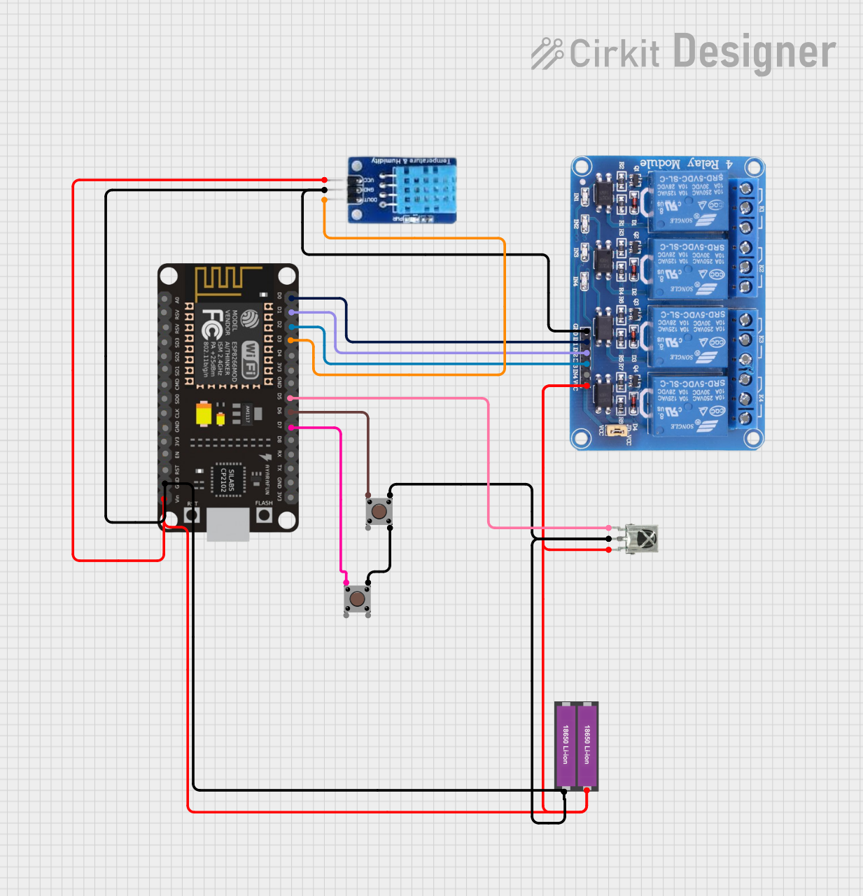

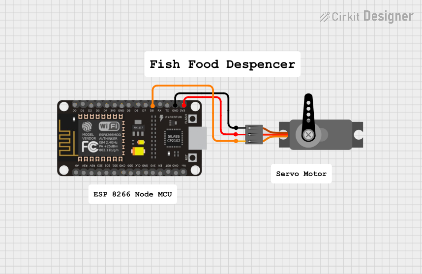

Explore Projects Built with ESP8266
Common Applications
- Smart home automation (e.g., controlling lights, thermostats, and appliances)
- Wireless sensor networks
- Remote data logging and monitoring
- IoT prototyping and development
- Wi-Fi-enabled robotics and drones
Technical Specifications
The ESP8266 is available in various module formats, with the ESP-01 being one of the most common. Below are the key technical details and pin configurations for the ESP-01 module.
Key Technical Details
| Parameter | Value |
|---|---|
| Operating Voltage | 3.0V - 3.6V |
| Operating Current | ~80mA (average), ~200mA (peak) |
| Wi-Fi Standards | 802.11 b/g/n |
| Processor | 32-bit Tensilica L106 @ 80 MHz |
| Flash Memory | 512 KB to 4 MB (module-dependent) |
| GPIO Pins | 2 (on ESP-01) |
| Communication Protocols | UART, SPI, I2C |
| Operating Temperature | -40°C to 125°C |
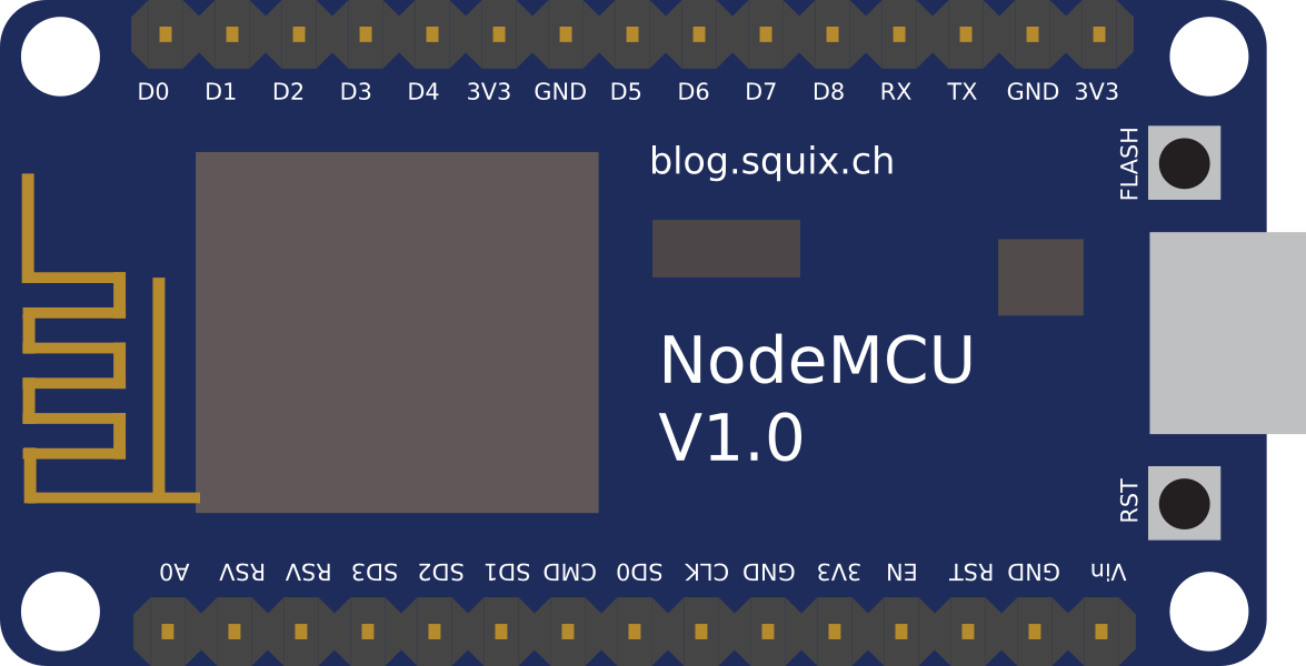
Pin Configuration (ESP-01 Module)
| Pin Name | Pin Number | Description |
|---|---|---|
| VCC | 1 | Power supply (3.3V) |
| GND | 2 | Ground |
| TX | 3 | UART Transmit (connect to RX of host device) |
| RX | 4 | UART Receive (connect to TX of host device) |
| CH_PD | 5 | Chip enable (connect to 3.3V for operation) |
| GPIO0 | 6 | General-purpose I/O pin |
| GPIO2 | 7 | General-purpose I/O pin |
| RST | 8 | Reset (active low) |
Usage Instructions
Connecting the ESP8266 to an Arduino UNO
To use the ESP8266 with an Arduino UNO, follow these steps:
- Power Supply: The ESP8266 operates at 3.3V. Use a voltage regulator or level shifter to ensure the Arduino's 5V logic does not damage the ESP8266.
- Wiring:
- Connect the ESP8266's
VCCandCH_PDpins to a 3.3V power source. - Connect
GNDto the ground of the Arduino. - Connect the
TXpin of the ESP8266 to a voltage divider (to step down the Arduino's 5V TX signal to 3.3V) and then to the Arduino's RX pin. - Connect the
RXpin of the ESP8266 to the Arduino's TX pin.
- Connect the ESP8266's
- Programming: Use the Arduino IDE to send AT commands or upload custom firmware to the ESP8266.
Example Code: Connecting to Wi-Fi
The following Arduino sketch demonstrates how to connect the ESP8266 to a Wi-Fi network using AT commands.
#include <SoftwareSerial.h>

// Create a SoftwareSerial object to communicate with the ESP8266
SoftwareSerial esp8266(2, 3); // RX, TX

void setup() {
  Serial.begin(9600); // Start serial communication with the PC
  esp8266.begin(9600); // Start serial communication with the ESP8266

  Serial.println("Initializing ESP8266...");

  // Send AT command to test communication
  sendCommand("AT", "OK");

  // Set Wi-Fi mode to station
  sendCommand("AT+CWMODE=1", "OK");

  // Connect to Wi-Fi network
  sendCommand("AT+CWJAP=\"YourSSID\",\"YourPassword\"", "OK");

  Serial.println("ESP8266 connected to Wi-Fi!");
}

void loop() {
  // Add your main code here
}

// Function to send AT commands and wait for a response
void sendCommand(String command, String expectedResponse) {
  esp8266.println(command); // Send the command to the ESP8266
  delay(2000); // Wait for the response

  while (esp8266.available()) {
    String response = esp8266.readString();
    Serial.println(response); // Print the response to the Serial Monitor

    if (response.indexOf(expectedResponse) != -1) {
      Serial.println("Command executed successfully.");
      return;
    }
  }

  Serial.println("Error: Expected response not received.");
}
Important Considerations
- Power Supply: Ensure the ESP8266 receives a stable 3.3V power supply. Using 5V directly can damage the module.
- Baud Rate: The default baud rate of the ESP8266 is 115200, but it can be changed using AT commands. Ensure the baud rate matches the Arduino's configuration.
- GPIO Usage: GPIO0 and GPIO2 are used for boot modes. Ensure they are in the correct state during power-up:
- GPIO0: HIGH for normal operation, LOW for firmware flashing.
- GPIO2: Must be HIGH during boot.
Troubleshooting and FAQs
Common Issues
ESP8266 Not Responding to AT Commands
- Solution: Check the wiring and ensure the ESP8266 is powered correctly. Verify the baud rate settings in the Arduino IDE.
Wi-Fi Connection Fails
- Solution: Double-check the SSID and password in the
AT+CWJAPcommand. Ensure the Wi-Fi network is within range.
- Solution: Double-check the SSID and password in the
Module Overheating
- Solution: Ensure the ESP8266 is not exposed to voltages above 3.6V. Use a proper voltage regulator if necessary.
Garbage Characters in Serial Monitor
- Solution: Ensure the baud rate in the Serial Monitor matches the ESP8266's baud rate.
FAQs
Can the ESP8266 be programmed directly without an Arduino?
- Yes, the ESP8266 can be programmed using the Arduino IDE or other tools by flashing custom firmware.
What is the maximum range of the ESP8266?
- The range depends on the environment but is typically around 50 meters indoors and 100 meters outdoors.
Can the ESP8266 operate on 5V?
- No, the ESP8266 requires a 3.3V power supply. Use a voltage regulator or level shifter for safe operation.
By following this documentation, users can effectively integrate the ESP8266 into their projects and troubleshoot common issues.