How to Use OPA2134: Examples, Pinouts, and Specs
Introduction
The OPA2134 is a high-performance, low-noise operational amplifier (op-amp) specifically designed for audio applications. It features ultra-low distortion, low noise, and a high slew rate, making it an excellent choice for high-fidelity audio signal processing. The OPA2134 is widely used in audio preamplifiers, active filters, equalizers, and other audio circuits where precision and sound quality are critical.
Explore Projects Built with OPA2134


Explore Projects Built with OPA2134
Common Applications and Use Cases
- High-fidelity audio preamplifiers
- Active filters and equalizers
- Audio mixing consoles
- Headphone amplifiers
- Digital-to-analog converter (DAC) output stages
- Audio signal conditioning circuits
Technical Specifications
The OPA2134 is a dual operational amplifier with the following key technical specifications:
| Parameter | Value |
|---|---|
| Supply Voltage Range | ±2.5V to ±18V (or 5V to 36V total) |
| Input Offset Voltage | 1mV (typical) |
| Input Bias Current | 5nA (typical) |
| Slew Rate | 20V/µs |
| Gain Bandwidth Product | 8 MHz |
| Total Harmonic Distortion + Noise (THD+N) | 0.00008% (typical) |
| Input Noise Density | 8 nV/√Hz |
| Output Drive Capability | ±35mA |
| Operating Temperature Range | -40°C to +85°C |
| Package Options | DIP-8, SOIC-8 |
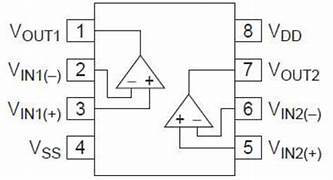
Pin Configuration and Descriptions
The OPA2134 is available in an 8-pin package. Below is the pinout and description:
| Pin Number | Pin Name | Description |
|---|---|---|
| 1 | OUT A | Output of Op-Amp A |
| 2 | IN- A | Inverting Input of Op-Amp A |
| 3 | IN+ A | Non-Inverting Input of Op-Amp A |
| 4 | V- (GND) | Negative Power Supply (or Ground) |
| 5 | IN+ B | Non-Inverting Input of Op-Amp B |
| 6 | IN- B | Inverting Input of Op-Amp B |
| 7 | OUT B | Output of Op-Amp B |
| 8 | V+ | Positive Power Supply |
Usage Instructions
The OPA2134 is straightforward to use in audio and general-purpose circuits. Below are the steps and considerations for using the component effectively:
How to Use the OPA2134 in a Circuit
- Power Supply: Connect the OPA2134 to a dual power supply (e.g., ±15V) or a single supply (e.g., 5V to 36V). Ensure proper decoupling capacitors (e.g., 0.1µF ceramic and 10µF electrolytic) are placed close to the power pins (V+ and V-).
- Input Configuration: Connect the input signal to the non-inverting (IN+) or inverting (IN-) input, depending on the desired circuit configuration (e.g., non-inverting amplifier, inverting amplifier, or buffer).
- Feedback Network: Design the feedback network (resistors and capacitors) to set the desired gain and frequency response. For example, in a non-inverting amplifier, the gain is determined by the ratio of the feedback resistor to the input resistor.
- Output Load: Ensure the load connected to the output does not exceed the OPA2134's drive capability (±35mA). For audio applications, this is typically a high-impedance load.
Important Considerations and Best Practices
- Power Supply Decoupling: Always use decoupling capacitors close to the power supply pins to minimize noise and ensure stable operation.
- Input Impedance: Use high-value resistors for the input network to maintain high input impedance and avoid loading the signal source.
- Thermal Management: The OPA2134 has low power dissipation, but ensure proper ventilation if used in high-temperature environments.
- Avoid Overloading: Do not exceed the maximum output current or supply voltage ratings to prevent damage to the device.
Example: Using OPA2134 with Arduino UNO
The OPA2134 can be used to amplify audio signals before feeding them into the Arduino's analog input. Below is an example of a simple non-inverting amplifier circuit with a gain of 11:
Circuit Description
- Input Signal: Connect an audio signal to the IN+ pin of the OPA2134.
- Feedback Network: Use a 10kΩ resistor (R1) between the output and IN- pin, and a 1kΩ resistor (R2) between IN- and ground. The gain is calculated as ( 1 + \frac{R1}{R2} = 11 ).
- Output: Connect the output of the OPA2134 to the Arduino's analog input (e.g., A0).
Arduino Code Example
// This code reads the amplified audio signal from the OPA2134 and prints
// the analog values to the Serial Monitor.

const int analogPin = A0; // Analog pin connected to OPA2134 output

void setup() {
  Serial.begin(9600); // Initialize serial communication at 9600 baud
}

void loop() {
  int analogValue = analogRead(analogPin); // Read the analog signal
  Serial.println(analogValue); // Print the value to the Serial Monitor
  delay(10); // Small delay for stability
}
Troubleshooting and FAQs
Common Issues and Solutions
No Output Signal:
- Cause: Incorrect power supply connections.
- Solution: Verify that the V+ and V- pins are connected to the correct supply voltages and that decoupling capacitors are in place.
Distorted Output:
- Cause: Overloading the output or incorrect feedback network design.
- Solution: Ensure the load impedance is within the OPA2134's drive capability and verify the feedback resistor values.
High Noise in Output:
- Cause: Poor power supply decoupling or external interference.
- Solution: Add decoupling capacitors close to the power pins and minimize long signal traces.
Excessive Heat:
- Cause: Overvoltage or excessive current draw.
- Solution: Ensure the supply voltage and output current are within the specified limits.
FAQs
Q1: Can the OPA2134 be used with a single power supply?
Yes, the OPA2134 can operate with a single supply (e.g., 5V to 36V). However, you may need to bias the input signal to a mid-supply voltage using a resistor divider.
Q2: Is the OPA2134 suitable for non-audio applications?
Yes, while optimized for audio, the OPA2134 can be used in other precision analog applications requiring low noise and distortion.
Q3: What is the maximum gain I can achieve with the OPA2134?
The maximum gain depends on the feedback network and the bandwidth of the signal. For high gains, ensure the gain-bandwidth product (8 MHz) is not exceeded.
Q4: Can I use the OPA2134 to drive headphones directly?
Yes, the OPA2134 can drive headphones with an impedance of 32Ω or higher, but for lower impedance headphones, consider using a dedicated headphone amplifier.