How to Use battery charger IC: Examples, Pinouts, and Specs
Introduction
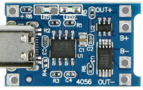
The TP4056 is a lithium-ion battery charger IC manufactured by Microchip Technology. It is designed to provide a complete constant-current/constant-voltage (CC/CV) linear charging solution for single-cell lithium-ion batteries. The IC is highly efficient, compact, and easy to use, making it a popular choice for portable electronics, power banks, and DIY projects.
Explore Projects Built with battery charger IC
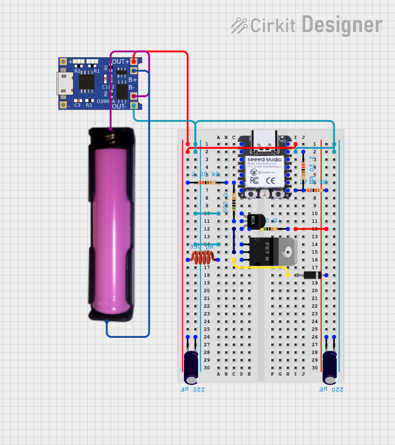


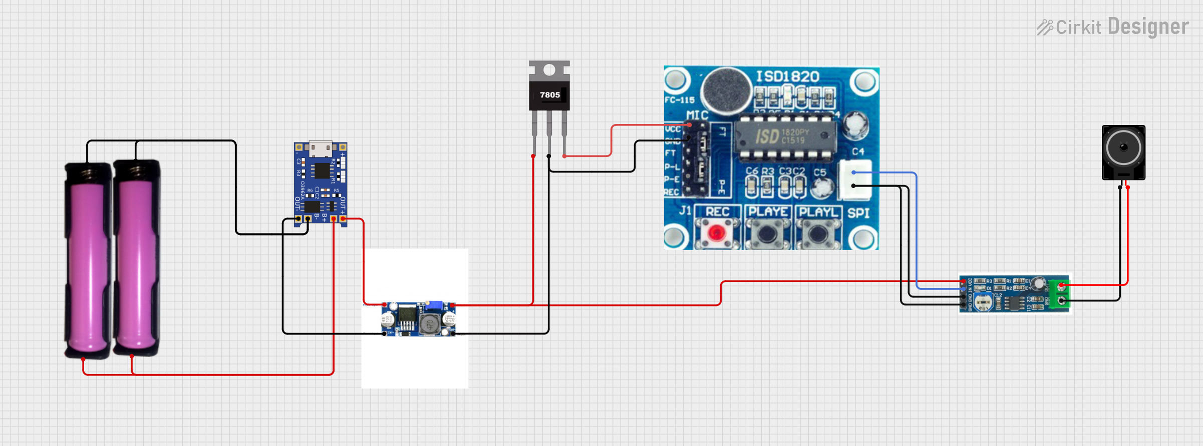
Explore Projects Built with battery charger IC
Common Applications and Use Cases
- Charging single-cell lithium-ion or lithium-polymer batteries
- Power banks and portable chargers
- Wearable devices and IoT gadgets
- DIY electronics projects
- Backup power systems
Technical Specifications
The TP4056 is a versatile and reliable IC with the following key specifications:
| Parameter | Value |
|---|---|
| Input Voltage Range | 4.0V to 8.0V |
| Charge Voltage | 4.2V ± 1% |
| Maximum Charge Current | Programmable up to 1A |
| Charge Termination | Automatic |
| Operating Temperature | -40°C to +85°C |
| Package Type | SOP-8 (Standard Small Outline Package) |
| Protection Features | Overvoltage, overcurrent, and thermal protection |
Pin Configuration and Descriptions
The TP4056 comes in an 8-pin SOP package. Below is the pinout and description:
| Pin Number | Pin Name | Description |
|---|---|---|
| 1 | TEMP | Temperature sense input. Connect to an NTC thermistor for battery temperature monitoring. |
| 2 | PROG | Programs the charge current. Connect a resistor to ground to set the desired current. |
| 3 | GND | Ground connection. |
| 4 | VCC | Input supply voltage. Connect to a DC source (4.0V to 8.0V). |
| 5 | BAT | Battery connection. Connect to the positive terminal of the lithium-ion battery. |
| 6 | STDBY | Status indicator output. Low when charging is complete. |
| 7 | CHRG | Status indicator output. Low when charging is in progress. |
| 8 | CE | Chip enable. Active low. Pull low to enable the IC, or high to disable it. |
Usage Instructions
How to Use the TP4056 in a Circuit
- Power Supply: Connect a DC power source (e.g., USB 5V) to the VCC pin. Ensure the input voltage is within the range of 4.0V to 8.0V.
- Battery Connection: Connect the positive terminal of the lithium-ion battery to the BAT pin and the negative terminal to GND.
- Programming Charge Current: Use a resistor (R_PROG) between the PROG pin and GND to set the desired charge current. The charge current (I_CHG) can be calculated using the formula: [ I_{CHG} = \frac{1200}{R_{PROG}} ] For example, a 1.2kΩ resistor sets the charge current to 1A.
- Status LEDs: Connect LEDs to the CHRG and STDBY pins (with appropriate current-limiting resistors) to monitor the charging status:
- CHRG pin: LED ON indicates charging in progress.
- STDBY pin: LED ON indicates charging is complete.
- Temperature Monitoring: Optionally, connect an NTC thermistor to the TEMP pin for battery temperature monitoring. If unused, connect TEMP to GND.
Important Considerations and Best Practices
- Thermal Management: Ensure proper heat dissipation, as the IC may heat up during high-current charging.
- Battery Safety: Use only with lithium-ion or lithium-polymer batteries that have built-in protection circuits.
- Input Voltage: Avoid exceeding the maximum input voltage of 8.0V to prevent damage to the IC.
- Capacitors: Place a 1µF ceramic capacitor close to the VCC pin and a 10µF capacitor near the BAT pin for stable operation.
Example: Using TP4056 with Arduino UNO
The TP4056 can be used with an Arduino UNO to monitor the charging status. Below is an example code snippet:
// TP4056 Status Monitoring with Arduino UNO
// Connect CHRG pin to Arduino pin 2 and STDBY pin to pin 3

const int chrgPin = 2;  // CHRG pin of TP4056
const int stdbyPin = 3; // STDBY pin of TP4056

void setup() {
  pinMode(chrgPin, INPUT);
  pinMode(stdbyPin, INPUT);
  Serial.begin(9600);
}

void loop() {
  int chrgStatus = digitalRead(chrgPin);  // Read CHRG pin status
  int stdbyStatus = digitalRead(stdbyPin); // Read STDBY pin status

  if (chrgStatus == LOW) {
    Serial.println("Charging in progress...");
  } else if (stdbyStatus == LOW) {
    Serial.println("Charging complete.");
  } else {
    Serial.println("No battery connected or idle state.");
  }

  delay(1000); // Wait for 1 second before checking again
}
Troubleshooting and FAQs
Common Issues and Solutions
IC Overheating
- Cause: High charge current or insufficient heat dissipation.
- Solution: Reduce the charge current by increasing the R_PROG resistor value. Ensure proper ventilation or add a heatsink.
Battery Not Charging
- Cause: Incorrect wiring or damaged battery.
- Solution: Verify all connections. Check the battery voltage and ensure it is within the acceptable range for charging.
Status LEDs Not Working
- Cause: Incorrect resistor values or faulty LEDs.
- Solution: Check the LED connections and use appropriate current-limiting resistors (e.g., 1kΩ).
Input Voltage Too High
- Cause: Power supply exceeds 8.0V.
- Solution: Use a regulated 5V power source, such as a USB adapter.
FAQs
Can the TP4056 charge multiple batteries in series?
- No, the TP4056 is designed for single-cell lithium-ion batteries only.
What happens if the TEMP pin is left floating?
- The IC may not function correctly. Connect TEMP to GND if temperature monitoring is not required.
Can I use the TP4056 with a solar panel?
- Yes, but ensure the solar panel's output voltage is within the 4.0V to 8.0V range and use a capacitor to stabilize the input.
How do I adjust the charge termination current?
- The termination current is typically 10% of the programmed charge current and cannot be directly adjusted.
By following this documentation, you can safely and effectively use the TP4056 battery charger IC in your projects.