How to Use ESP32-S3 EC200U: Examples, Pinouts, and Specs
Introduction
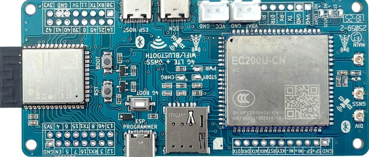
The ESP32-S3 EC200U is a powerful and versatile microcontroller module that combines the ESP32-S3's advanced processing capabilities with the EC200U LTE module for cellular connectivity. This component is ideal for IoT applications requiring both Wi-Fi and LTE connectivity, offering a robust solution for remote monitoring, data transmission, and edge computing.
Explore Projects Built with ESP32-S3 EC200U


Explore Projects Built with ESP32-S3 EC200U
Common Applications and Use Cases
- IoT devices with dual connectivity (Wi-Fi and LTE)
- Remote monitoring and control systems
- Smart agriculture and environmental monitoring
- Industrial automation and telemetry
- Asset tracking and fleet management
Technical Specifications
Key Technical Details
| Parameter | Specification |
|---|---|
| Microcontroller | ESP32-S3 (Xtensa® 32-bit LX7 dual-core processor) |
| Cellular Module | EC200U (LTE Cat 4 module) |
| Wi-Fi | 802.11 b/g/n (2.4 GHz) |
| Bluetooth | Bluetooth 5.0 (LE) |
| Flash Memory | Up to 16 MB |
| SRAM | 512 KB |
| Operating Voltage | 3.3V |
| GPIO Pins | Up to 45 |
| LTE Bands | Supports multiple LTE bands (region-specific) |
| UART Interfaces | 3 UARTs |
| SPI Interfaces | 2 SPIs |
| I2C Interfaces | 2 I2Cs |
| Power Consumption | Ultra-low power in deep sleep mode |
| Operating Temperature | -40°C to +85°C |
Pin Configuration and Descriptions
| Pin Number | Pin Name | Description |
|---|---|---|
| 1 | VCC | Power supply input (3.3V) |
| 2 | GND | Ground |
| 3 | TXD0 | UART0 Transmit Data |
| 4 | RXD0 | UART0 Receive Data |
| 5 | GPIO0 | General-purpose I/O pin |
| 6 | GPIO1 | General-purpose I/O pin |
| 7 | EN | Enable pin (active high) |
| 8 | LTE_TX | LTE module transmit pin |
| 9 | LTE_RX | LTE module receive pin |
| 10 | ANT | LTE antenna connection |
Note: The pin configuration may vary slightly depending on the specific ESP32-S3 EC200U module variant. Always refer to the manufacturer's datasheet for precise details.
Usage Instructions
How to Use the Component in a Circuit
- Power Supply: Connect the VCC pin to a stable 3.3V power source and GND to ground.
- Wi-Fi and Bluetooth: Use the ESP32-S3's built-in Wi-Fi and Bluetooth capabilities for local connectivity.
- LTE Connectivity: Connect the LTE_TX and LTE_RX pins to the EC200U module for cellular communication. Attach an appropriate LTE antenna to the ANT pin.
- GPIO Usage: Configure GPIO pins as needed for sensors, actuators, or other peripherals.
- Programming: Use the ESP-IDF (Espressif IoT Development Framework) or Arduino IDE to program the ESP32-S3 EC200U.
Important Considerations and Best Practices
- Ensure the power supply is stable and within the specified voltage range (3.3V).
- Use decoupling capacitors near the VCC pin to reduce noise and improve stability.
- For LTE connectivity, ensure the antenna is properly connected and positioned for optimal signal strength.
- Avoid using GPIO pins that are reserved for internal functions unless explicitly allowed in the datasheet.
- When programming, ensure the correct board and module settings are selected in your development environment.
Example Code for Arduino UNO Integration
Below is an example of how to use the ESP32-S3 EC200U with an Arduino UNO for basic LTE communication:
#include <SoftwareSerial.h>

// Define RX and TX pins for communication with ESP32-S3 EC200U
SoftwareSerial espSerial(10, 11); // RX = Pin 10, TX = Pin 11

void setup() {
  Serial.begin(9600); // Initialize serial monitor
  espSerial.begin(115200); // Initialize ESP32-S3 EC200U communication

  Serial.println("Initializing ESP32-S3 EC200U...");
  delay(2000);

  // Send AT command to check LTE module status
  espSerial.println("AT");
  delay(1000);

  // Read response from ESP32-S3 EC200U
  while (espSerial.available()) {
    String response = espSerial.readString();
    Serial.println("Response: " + response);
  }
}

void loop() {
  // Continuously check for incoming data from ESP32-S3 EC200U
  if (espSerial.available()) {
    String data = espSerial.readString();
    Serial.println("Received: " + data);
  }

  // Example: Send data to ESP32-S3 EC200U
  if (Serial.available()) {
    String command = Serial.readString();
    espSerial.println(command);
  }
}
Note: Replace pins 10 and 11 with the appropriate pins on your Arduino UNO. Ensure the ESP32-S3 EC200U is properly connected to the Arduino.
Troubleshooting and FAQs
Common Issues and Solutions
No Response from LTE Module:
- Ensure the LTE antenna is securely connected.
- Verify the power supply voltage is stable at 3.3V.
- Check the UART connections (TX and RX) for proper wiring.
Wi-Fi or Bluetooth Not Working:
- Confirm that the ESP32-S3 firmware is correctly flashed.
- Ensure the Wi-Fi or Bluetooth antenna (if external) is properly connected.
Module Not Powering On:
- Check the EN pin to ensure it is pulled high.
- Verify the power supply and ground connections.
AT Commands Not Recognized:
- Ensure the correct baud rate is set for UART communication.
- Check for firmware updates for the EC200U module.
FAQs
Can the ESP32-S3 EC200U operate without LTE connectivity? Yes, the ESP32-S3 can function independently using its Wi-Fi and Bluetooth capabilities.
What development tools are recommended for programming? The ESP-IDF and Arduino IDE are the most commonly used tools for programming the ESP32-S3 EC200U.
Is the module compatible with 5V logic? No, the ESP32-S3 EC200U operates at 3.3V logic levels. Use level shifters if interfacing with 5V devices.
How do I update the firmware? Use the Espressif Flash Download Tool or other compatible tools to update the ESP32-S3 firmware. For the EC200U, refer to Quectel's firmware update guidelines.
By following this documentation, users can effectively integrate and utilize the ESP32-S3 EC200U in their projects.