How to Use Portenta mid carrier: Examples, Pinouts, and Specs
Introduction
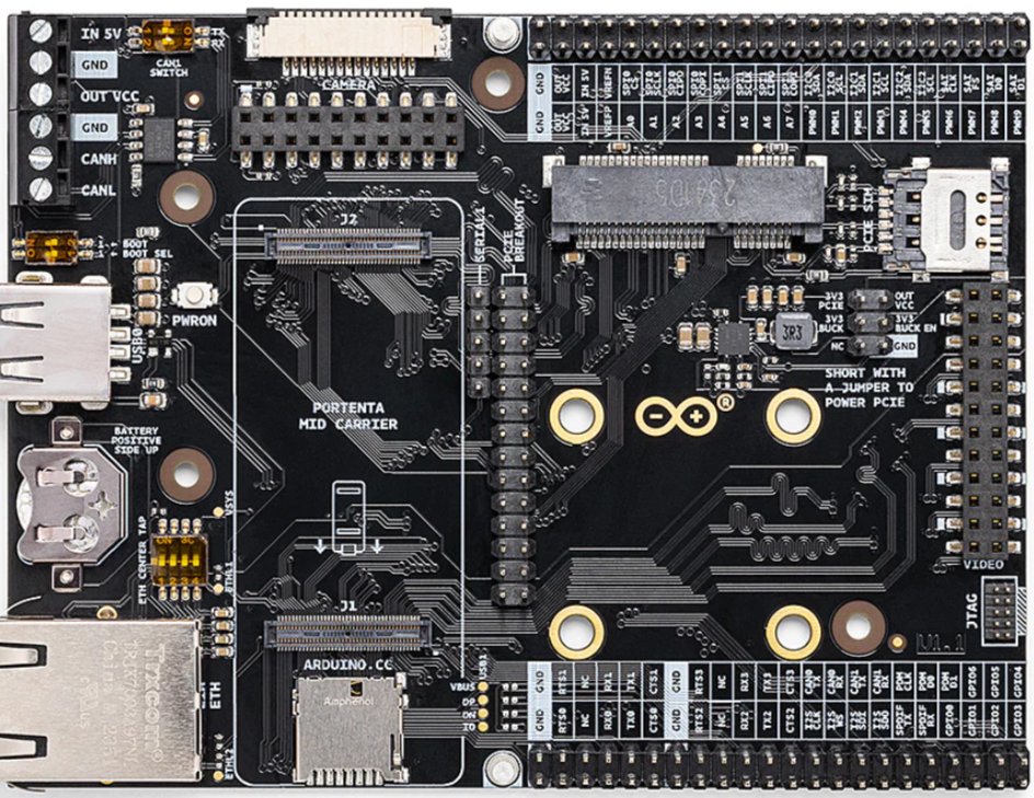
The Portenta Mid Carrier (Manufacturer Part ID: WD-M E363740) is a versatile carrier board designed by Arduino to expand the functionality of the Portenta H7 microcontroller. This carrier board provides a wide range of connectivity options, including GPIO, I2C, SPI, UART, and more, making it an ideal choice for prototyping and integrating sensors, peripherals, and other hardware components. Its compact design and robust features make it suitable for industrial, IoT, and embedded applications.
Explore Projects Built with Portenta mid carrier


Explore Projects Built with Portenta mid carrier
Common Applications and Use Cases
- IoT Prototyping: Connect sensors and actuators for IoT applications.
- Industrial Automation: Interface with industrial-grade peripherals and devices.
- Robotics: Enable communication with motors, encoders, and other robotic components.
- Embedded Systems Development: Simplify hardware integration for embedded projects.
- Educational Projects: Provide a hands-on platform for learning advanced electronics.
Technical Specifications
Key Technical Details
| Parameter | Specification |
|---|---|
| Manufacturer | Arduino |
| Part ID | WD-M E363740 |
| Compatible MCU | Arduino Portenta H7 |
| Power Supply | 5V (via USB-C) or external power supply (up to 12V) |
| Connectivity Options | GPIO, I2C, SPI, UART, CAN, PWM, ADC, DAC |
| USB Ports | USB-C (for power and data) |
| Expansion Ports | High-density connectors for Portenta H7 |
| Dimensions | 90mm x 60mm |
| Operating Temperature | -40°C to 85°C |
| Mounting Options | Screw holes for secure mounting |
Pin Configuration and Descriptions
The Portenta Mid Carrier provides access to a variety of pins through its connectors. Below is a summary of the key pin configurations:
GPIO and Communication Pins
| Pin Name | Type | Description |
|---|---|---|
| GPIO0-GPIO13 | Digital I/O | General-purpose digital input/output pins. |
| I2C_SCL | I2C Clock | Clock line for I2C communication. |
| I2C_SDA | I2C Data | Data line for I2C communication. |
| SPI_MOSI | SPI Data Out | Master Out Slave In (MOSI) for SPI communication. |
| SPI_MISO | SPI Data In | Master In Slave Out (MISO) for SPI communication. |
| SPI_SCK | SPI Clock | Clock line for SPI communication. |
| UART_TX | UART Transmit | Transmit line for UART communication. |
| UART_RX | UART Receive | Receive line for UART communication. |
| CAN_H | CAN High | High line for CAN bus communication. |
| CAN_L | CAN Low | Low line for CAN bus communication. |
Power and Analog Pins
| Pin Name | Type | Description |
|---|---|---|
| VIN | Power Input | External power input (5V to 12V). |
| 3V3 | Power Output | 3.3V regulated output for peripherals. |
| GND | Ground | Ground connection. |
| ADC0-ADC3 | Analog Input | Analog-to-digital converter inputs (12-bit resolution). |
| DAC0-DAC1 | Analog Output | Digital-to-analog converter outputs. |
Usage Instructions
How to Use the Portenta Mid Carrier in a Circuit
- Connect the Portenta H7: Attach the Portenta H7 microcontroller to the high-density connectors on the carrier board.
- Power the Board: Supply power via the USB-C port or an external power source (5V to 12V) connected to the VIN pin.
- Connect Peripherals: Use the GPIO, I2C, SPI, UART, or other pins to connect sensors, actuators, or other peripherals.
- Program the Portenta H7: Write and upload your code to the Portenta H7 using the Arduino IDE or other compatible development environments.
- Monitor and Debug: Use the USB-C port for serial communication and debugging.
Important Considerations and Best Practices
- Power Supply: Ensure the power supply voltage does not exceed the specified range (5V to 12V) to avoid damaging the board.
- Pin Voltage Levels: The GPIO pins operate at 3.3V logic levels. Use level shifters if interfacing with 5V devices.
- Static Protection: Handle the board with care to avoid electrostatic discharge (ESD) damage.
- Secure Mounting: Use the screw holes to securely mount the board in your project enclosure.
Example: Using the Portenta Mid Carrier with Arduino UNO Code
Below is an example of interfacing a temperature sensor (e.g., TMP36) with the Portenta Mid Carrier using the ADC pin:
// Example: Reading temperature data from a TMP36 sensor
// Connect the TMP36 sensor's VCC to 3V3, GND to GND, and OUT to ADC0.

const int tempSensorPin = A0; // TMP36 connected to ADC0
float voltage = 0.0;
float temperatureC = 0.0;

void setup() {
  Serial.begin(9600); // Initialize serial communication
  pinMode(tempSensorPin, INPUT); // Set ADC0 as input
}

void loop() {
  int sensorValue = analogRead(tempSensorPin); // Read analog value from TMP36
  voltage = sensorValue * (3.3 / 4095.0); // Convert to voltage (12-bit ADC)
  temperatureC = (voltage - 0.5) * 100.0; // Convert voltage to temperature (Celsius)

  Serial.print("Temperature: ");
  Serial.print(temperatureC);
  Serial.println(" °C");

  delay(1000); // Wait 1 second before next reading
}
Troubleshooting and FAQs
Common Issues and Solutions
Board Not Powering On
- Cause: Insufficient or incorrect power supply.
- Solution: Verify the power source is within the 5V to 12V range and properly connected.
Peripherals Not Responding
- Cause: Incorrect pin connections or configuration.
- Solution: Double-check the wiring and ensure the correct pins are used in the code.
Communication Protocols Not Working
- Cause: Mismatched voltage levels or incorrect settings.
- Solution: Use level shifters if needed and verify protocol configurations in the code.
Overheating
- Cause: Excessive current draw from peripherals.
- Solution: Ensure connected devices do not exceed the board's power output limits.
FAQs
Can I use the Portenta Mid Carrier with other microcontrollers?
- No, the carrier board is specifically designed for the Arduino Portenta H7.
What is the maximum current output of the 3V3 pin?
- The 3V3 pin can supply up to 500mA, depending on the power source.
Is the board compatible with Arduino shields?
- No, the Portenta Mid Carrier does not support standard Arduino shields due to its unique design.
Can I use the board in outdoor environments?
- Yes, but ensure the board is protected from moisture and extreme conditions.
This concludes the documentation for the Portenta Mid Carrier. For further assistance, refer to the official Arduino documentation or community forums.