How to Use Sound Sensor Module: Examples, Pinouts, and Specs
Introduction
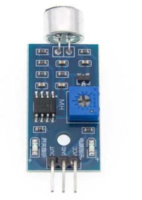
The Sound Sensor Module, based on the LM393 comparator from STMicroelectronics, is a device designed to detect sound levels and convert them into an electrical signal. It is widely used in sound detection and analysis projects, such as voice-activated systems, noise monitoring, and audio-based automation. The module is capable of detecting sound intensity and can output both analog and digital signals, making it versatile for various applications.
Explore Projects Built with Sound Sensor Module
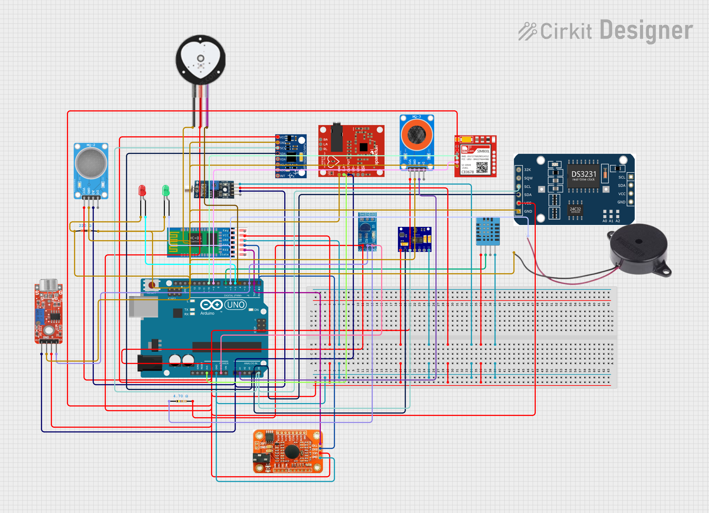
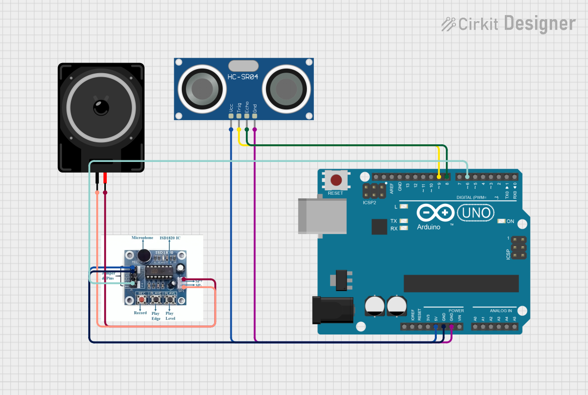
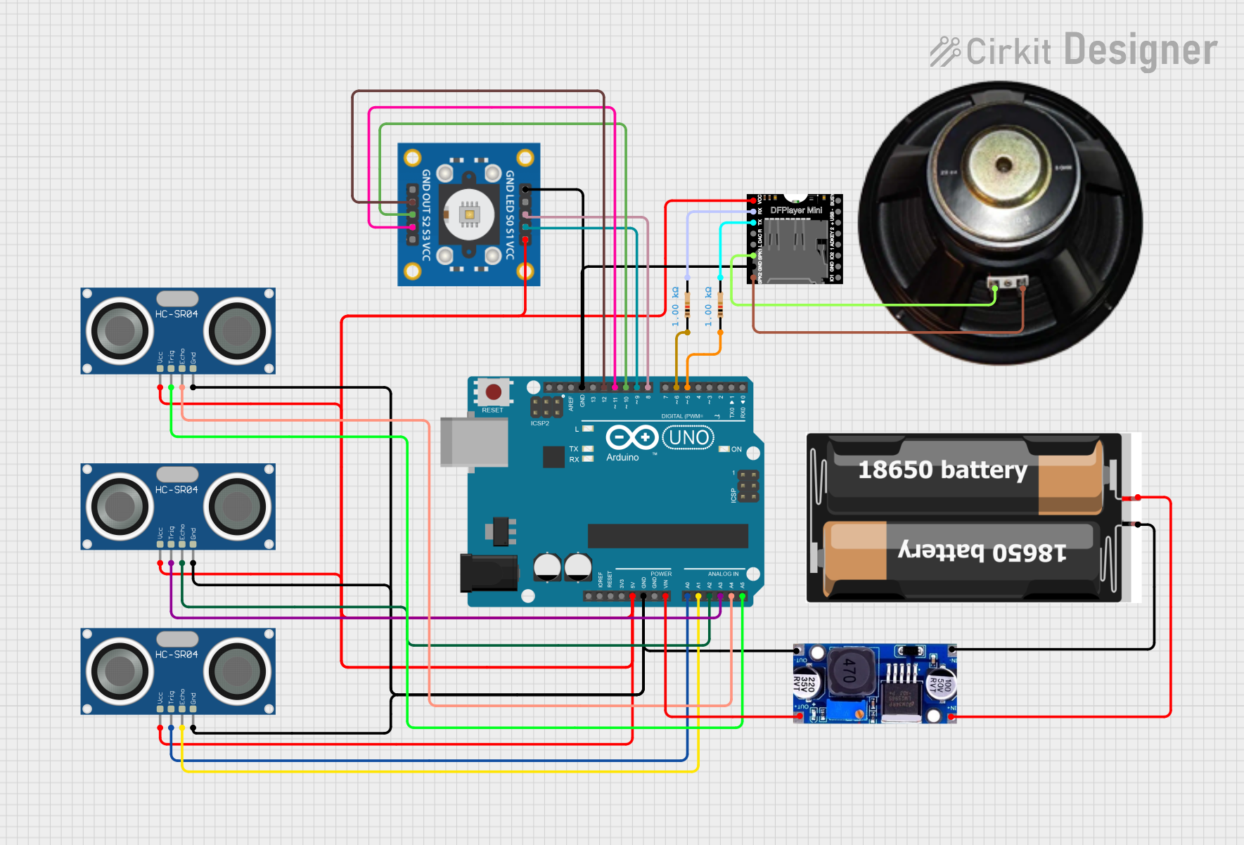

Explore Projects Built with Sound Sensor Module
Common Applications and Use Cases
- Voice-activated devices and systems
- Noise level monitoring and control
- Audio-based automation (e.g., clapping to turn on/off lights)
- Sound-triggered alarms or notifications
- Robotics and interactive projects
Technical Specifications
The following are the key technical details of the Sound Sensor Module:
| Parameter | Value |
|---|---|
| Manufacturer | STMicroelectronics |
| Part ID | LM393 |
| Operating Voltage | 3.3V to 5V |
| Output Type | Analog and Digital |
| Digital Output Threshold | Adjustable via onboard potentiometer |
| Microphone Type | Electret Condenser Microphone |
| Dimensions | ~32mm x 15mm |
| Operating Temperature | -40°C to +85°C |
Pin Configuration and Descriptions
The Sound Sensor Module typically has 4 pins. The table below describes each pin:
| Pin Name | Description |
|---|---|
| VCC | Power supply pin. Connect to 3.3V or 5V. |
| GND | Ground pin. Connect to the ground of the circuit. |
| A0 | Analog output pin. Outputs a voltage proportional to the detected sound level. |
| D0 | Digital output pin. Outputs HIGH or LOW based on the sound threshold set via the potentiometer. |
Usage Instructions
How to Use the Component in a Circuit
- Power the Module: Connect the
VCCpin to a 3.3V or 5V power source and theGNDpin to the ground. - Connect Outputs:
- For analog sound level detection, connect the
A0pin to an analog input pin of your microcontroller. - For digital sound detection, connect the
D0pin to a digital input pin of your microcontroller.
- For analog sound level detection, connect the
- Adjust Sensitivity: Use the onboard potentiometer to adjust the sensitivity of the digital output. Turning the potentiometer clockwise increases sensitivity, while turning it counterclockwise decreases it.
- Test the Module: Generate sound near the microphone and observe the outputs. The
D0pin will toggle HIGH or LOW based on the sound threshold, and theA0pin will output a varying voltage corresponding to the sound intensity.
Important Considerations and Best Practices
- Power Supply: Ensure the module is powered within its operating voltage range (3.3V to 5V). Exceeding this range may damage the module.
- Noise Isolation: Place the module away from high-frequency noise sources to avoid interference.
- Potentiometer Adjustment: Fine-tune the potentiometer for optimal sensitivity based on your application.
- Microphone Placement: Position the microphone to face the sound source for better detection accuracy.
Example Code for Arduino UNO
Below is an example of how to use the Sound Sensor Module with an Arduino UNO to read both analog and digital outputs:
// Define pin connections
const int analogPin = A0;  // Connect A0 pin of the module to A0 on Arduino
const int digitalPin = 2;  // Connect D0 pin of the module to digital pin 2
const int ledPin = 13;     // Built-in LED for visual feedback

void setup() {
  pinMode(digitalPin, INPUT);  // Set digital pin as input
  pinMode(ledPin, OUTPUT);     // Set LED pin as output
  Serial.begin(9600);          // Initialize serial communication
}

void loop() {
  // Read analog value from the sound sensor
  int soundLevel = analogRead(analogPin);

  // Read digital value from the sound sensor
  int soundDetected = digitalRead(digitalPin);

  // Print the analog sound level to the Serial Monitor
  Serial.print("Analog Sound Level: ");
  Serial.println(soundLevel);

  // Check if sound is detected (digital output is HIGH)
  if (soundDetected == HIGH) {
    digitalWrite(ledPin, HIGH);  // Turn on LED if sound is detected
    Serial.println("Sound Detected!");
  } else {
    digitalWrite(ledPin, LOW);   // Turn off LED if no sound is detected
  }

  delay(100);  // Small delay for stability
}
Troubleshooting and FAQs
Common Issues and Solutions
No Output from the Module:
- Ensure the module is powered correctly (3.3V to 5V).
- Check all connections for loose wires or incorrect pin assignments.
- Verify that the potentiometer is not set too low (insensitive) or too high (overly sensitive).
Inconsistent Digital Output:
- Adjust the potentiometer to fine-tune the sensitivity.
- Ensure the microphone is not exposed to constant background noise.
Analog Output Not Changing:
- Verify that the
A0pin is connected to an analog input pin on the microcontroller. - Check if the sound source is loud enough to be detected.
- Verify that the
Interference from Other Devices:
- Place the module away from high-frequency noise sources, such as motors or wireless transmitters.
- Use shielded cables for connections if interference persists.
FAQs
Q: Can the module detect specific frequencies of sound?
A: No, the module is designed to detect sound intensity, not specific frequencies. For frequency analysis, consider using a dedicated audio processing module.
Q: How far can the module detect sound?
A: The detection range depends on the sound intensity and the sensitivity setting of the potentiometer. Typically, it can detect sounds within a few meters.
Q: Can I use the module with a 3.3V microcontroller?
A: Yes, the module operates within a voltage range of 3.3V to 5V, making it compatible with 3.3V microcontrollers like the ESP32.
Q: Is the module suitable for outdoor use?
A: The module is not weatherproof. For outdoor use, ensure it is protected from moisture and extreme temperatures.
By following this documentation, you can effectively integrate the Sound Sensor Module into your projects for sound detection and analysis.