
How to Use NRF24LU1: Examples, Pinouts, and Specs
 Design with NRF24LU1 in Cirkit Designer
Introduction
The NRF24LU1 is a low-power, 2.4 GHz transceiver with an integrated microcontroller, designed for wireless communication in a variety of applications. It combines a high-performance RF transceiver with an 8-bit microcontroller, making it a versatile solution for wireless data transmission. The component supports multiple data rates (up to 2 Mbps) and features a simple SPI interface for seamless integration into embedded systems.
Explore Projects Built with NRF24LU1
 Open Project in Cirkit Designer
 Open Project in Cirkit Designer
 Open Project in Cirkit Designer
 Open Project in Cirkit Designer
Explore Projects Built with NRF24LU1
Open Project in Cirkit DesignerOpen Project in Cirkit DesignerOpen Project in Cirkit DesignerOpen Project in Cirkit DesignerCommon Applications and Use Cases
- Wireless remote controls
- IoT (Internet of Things) devices
- Wireless sensors and monitoring systems
- Home automation
- Wireless gaming peripherals
- Industrial wireless communication
Technical Specifications
Key Technical Details
| Parameter | Value |
|---|---|
| Frequency Range | 2.4 GHz ISM band |
| Data Rate | 250 kbps, 1 Mbps, 2 Mbps |
| Operating Voltage | 1.9 V to 3.6 V |
| Current Consumption | 11.3 mA (RX mode), 10.5 mA (TX mode @ 0 dBm) |
| Sleep Mode Current | 2.5 µA |
| Microcontroller Core | Enhanced 8051 |
| Flash Memory | 16 kB |
| RAM | 1 kB |
| GPIO Pins | 12 configurable pins |
| Communication Interface | SPI |
| Operating Temperature | -40°C to +85°C |
Pin Configuration and Descriptions
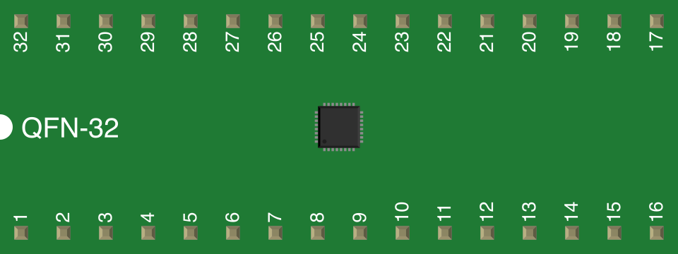
The NRF24LU1 is available in a 32-pin QFN package. Below is the pin configuration:
| Pin Number | Pin Name | Description |
|---|---|---|
| 1 | VDD | Power supply (1.9 V to 3.6 V) |
| 2 | GND | Ground |
| 3 | P0.0 | GPIO pin 0 / SPI MISO |
| 4 | P0.1 | GPIO pin 1 / SPI MOSI |
| 5 | P0.2 | GPIO pin 2 / SPI SCK |
| 6 | P0.3 | GPIO pin 3 / SPI CSN |
| 7 | P0.4 | GPIO pin 4 |
| 8 | P0.5 | GPIO pin 5 |
| 9 | P0.6 | GPIO pin 6 |
| 10 | P0.7 | GPIO pin 7 |
| 11 | RESET | Reset pin |
| 12 | XTAL1 | Crystal oscillator input |
| 13 | XTAL2 | Crystal oscillator output |
| 14 | ANT1 | RF antenna connection 1 |
| 15 | ANT2 | RF antenna connection 2 |
| 16-32 | Reserved | Reserved pins (do not connect) |
Usage Instructions
How to Use the NRF24LU1 in a Circuit
- Power Supply: Connect the VDD pin to a stable power source (1.9 V to 3.6 V) and the GND pin to ground.
- Antenna Connection: Attach a suitable 2.4 GHz antenna to the ANT1 and ANT2 pins for optimal RF performance.
- SPI Communication: Use the SPI interface (MISO, MOSI, SCK, CSN) to communicate with the NRF24LU1. Ensure proper configuration of the SPI clock and data rates.
- Microcontroller Programming: Program the integrated 8051 microcontroller using the provided development tools and libraries.
- Crystal Oscillator: Connect a 16 MHz crystal oscillator to the XTAL1 and XTAL2 pins for clock generation.
Important Considerations and Best Practices
- Use decoupling capacitors (e.g., 0.1 µF) near the VDD pin to reduce noise and ensure stable operation.
- Keep the antenna traces as short as possible and follow RF design guidelines to minimize signal loss.
- Avoid placing the NRF24LU1 near high-frequency components or noisy power supplies to prevent interference.
- Ensure proper grounding and shielding for reliable wireless communication.
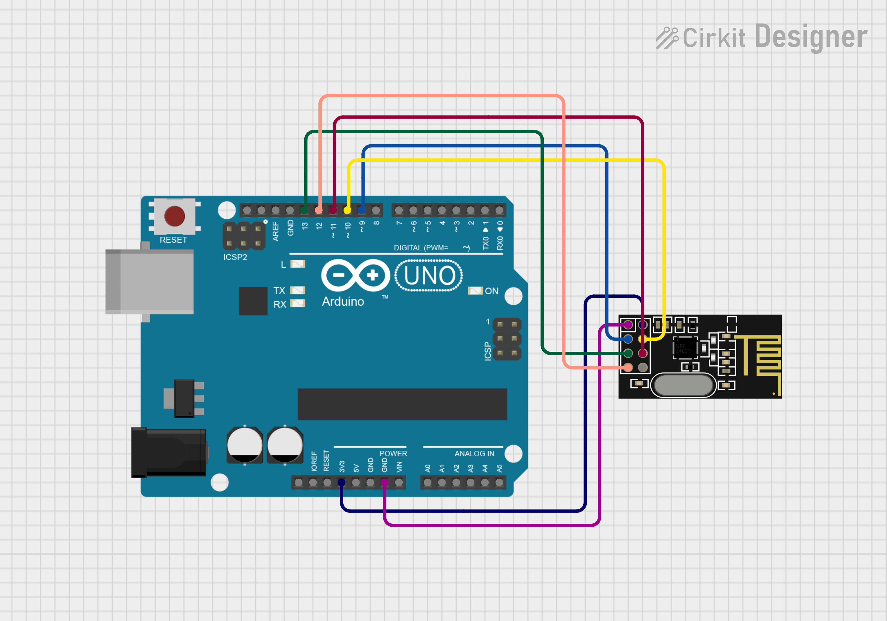
Example Code for Arduino UNO
The NRF24LU1 can be interfaced with an Arduino UNO using the SPI interface. Below is an example code snippet to initialize communication:
#include <SPI.h>

// Define SPI pins for NRF24LU1
#define CSN_PIN 10  // Chip Select Not (CSN) pin
#define SCK_PIN 13  // Serial Clock (SCK) pin
#define MOSI_PIN 11 // Master Out Slave In (MOSI) pin
#define MISO_PIN 12 // Master In Slave Out (MISO) pin

void setup() {
  // Initialize SPI communication
  SPI.begin();

  // Set CSN pin as output
  pinMode(CSN_PIN, OUTPUT);

  // Set CSN high to deselect the NRF24LU1
  digitalWrite(CSN_PIN, HIGH);

  // Begin serial communication for debugging
  Serial.begin(9600);
  Serial.println("NRF24LU1 Initialization Complete");
}

void loop() {
  // Example: Send a command to the NRF24LU1
  digitalWrite(CSN_PIN, LOW); // Select the NRF24LU1
  SPI.transfer(0x00);         // Send a dummy command (replace with actual command)
  digitalWrite(CSN_PIN, HIGH); // Deselect the NRF24LU1

  delay(1000); // Wait for 1 second
}
Troubleshooting and FAQs
Common Issues and Solutions
No Communication with NRF24LU1:
- Ensure the SPI connections (MISO, MOSI, SCK, CSN) are correctly wired.
- Verify that the SPI clock speed is compatible with the NRF24LU1.
Poor Wireless Range:
- Check the antenna connections and ensure proper placement.
- Avoid obstructions or interference from other 2.4 GHz devices.
High Power Consumption:
- Ensure the NRF24LU1 is entering sleep mode when not in use.
- Use low-power modes in your firmware to reduce energy consumption.
Unstable Operation:
- Verify the power supply voltage is within the specified range (1.9 V to 3.6 V).
- Add decoupling capacitors near the VDD pin to stabilize the power supply.
FAQs
Q: Can the NRF24LU1 be used without an external microcontroller?
A: Yes, the NRF24LU1 has an integrated 8051 microcontroller, allowing it to operate independently in many applications.
Q: What is the maximum data rate supported by the NRF24LU1?
A: The NRF24LU1 supports data rates of up to 2 Mbps.
Q: Is the NRF24LU1 compatible with other NRF24 series transceivers?
A: Yes, the NRF24LU1 is compatible with other NRF24 series devices, such as the NRF24L01, for wireless communication.
Q: What type of antenna should I use with the NRF24LU1?
A: A 2.4 GHz PCB trace antenna, chip antenna, or external whip antenna can be used, depending on your design requirements.