
How to Use MIDI_CONN_FEMALE_SUPPORT: Examples, Pinouts, and Specs
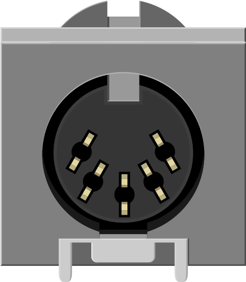
 Design with MIDI_CONN_FEMALE_SUPPORT in Cirkit Designer
Introduction
The MIDI_CONN_FEMALE_SUPPORT is a female MIDI connector manufactured by SparkFun, designed to interface with MIDI (Musical Instrument Digital Interface) devices. It facilitates the transmission of musical data and control signals, making it an essential component in audio and music production systems. This connector is typically used to receive MIDI signals from male connectors, ensuring reliable communication between MIDI-enabled devices.
Explore Projects Built with MIDI_CONN_FEMALE_SUPPORT
 Open Project in Cirkit Designer
 Open Project in Cirkit Designer
 Open Project in Cirkit Designer
 Open Project in Cirkit Designer
Explore Projects Built with MIDI_CONN_FEMALE_SUPPORT
Open Project in Cirkit DesignerOpen Project in Cirkit DesignerOpen Project in Cirkit DesignerOpen Project in Cirkit DesignerCommon Applications and Use Cases
- Connecting MIDI keyboards, synthesizers, and controllers to other MIDI devices.
- Integrating MIDI interfaces with computers or audio equipment.
- Building custom MIDI hardware projects.
- Repairing or replacing MIDI input ports on existing devices.
Technical Specifications
The following table outlines the key technical details of the MIDI_CONN_FEMALE_SUPPORT:
| Parameter | Value |
|---|---|
| Manufacturer | SparkFun |
| Part ID | MIDI_CONN_FEMALE_SUPPORT |
| Connector Type | 5-pin DIN Female |
| Voltage Rating | 5V DC (typical for MIDI signals) |
| Current Rating | 5mA (typical MIDI signal current) |
| Mounting Style | Through-hole |
| Dimensions | 15.5mm x 12.5mm x 10mm |
| Operating Temperature | -20°C to +70°C |
Pin Configuration and Descriptions
The MIDI_CONN_FEMALE_SUPPORT features a standard 5-pin DIN configuration. The pinout is as follows:
| Pin Number | Name | Description |
|---|---|---|
| 1 | Shield Ground | Connects to the cable shield for grounding and noise reduction. |
| 2 | Not Connected | Reserved; typically not used in standard MIDI applications. |
| 3 | Shield Ground | Alternate ground connection (redundant with Pin 1). |
| 4 | MIDI Data (+) | Positive MIDI signal line; transmits data to the receiving device. |
| 5 | MIDI Data (-) | Negative MIDI signal line; complements the positive signal for differential use. |
Usage Instructions
How to Use the Component in a Circuit
Mounting the Connector:
- Solder the MIDI_CONN_FEMALE_SUPPORT onto a PCB using its through-hole pins. Ensure proper alignment with the PCB layout.
- Verify that the solder joints are clean and secure to avoid signal interruptions.
Connecting to a MIDI Circuit:
- Connect Pin 4 (MIDI Data +) to the MIDI signal output of the transmitting device.
- Connect Pin 5 (MIDI Data -) to the complementary signal line.
- Use Pin 1 or Pin 3 for grounding the circuit.
- Ensure that the circuit includes a 220-ohm resistor in series with the MIDI signal lines to comply with the MIDI standard.
Power Requirements:
- MIDI devices typically operate at 5V DC. Ensure that the circuit provides the correct voltage and current levels.
Important Considerations and Best Practices
- Cable Shielding: Use shielded cables to minimize noise and interference in MIDI signals.
- Signal Integrity: Avoid long cable runs to prevent signal degradation. The MIDI standard recommends a maximum cable length of 15 meters.
- Polarity: Double-check the polarity of the connections to avoid damaging the connected devices.
- Compliance: Follow the MIDI standard specifications for circuit design to ensure compatibility with other MIDI devices.
Example: Connecting to an Arduino UNO
The MIDI_CONN_FEMALE_SUPPORT can be used with an Arduino UNO to receive MIDI signals. Below is an example circuit and code:
Circuit Diagram
- Connect Pin 4 of the MIDI connector to Arduino digital pin 2 through a 220-ohm resistor.
- Connect Pin 5 of the MIDI connector to ground.
- Connect Pin 1 (or Pin 3) to the Arduino ground.
Arduino Code
// MIDI Receiver Example for Arduino UNO
// This code reads MIDI messages from the MIDI_CONN_FEMALE_SUPPORT connector
// and prints them to the Serial Monitor.

const int midiPin = 2; // MIDI Data (+) connected to digital pin 2

void setup() {
  pinMode(midiPin, INPUT); // Set MIDI pin as input
  Serial.begin(31250);     // MIDI standard baud rate
}

void loop() {
  if (Serial.available() > 0) {
    // Read incoming MIDI byte
    byte midiByte = Serial.read();
    // Print the MIDI byte to the Serial Monitor
    Serial.print("MIDI Byte Received: ");
    Serial.println(midiByte, HEX);
  }
}
Troubleshooting and FAQs
Common Issues Users Might Face
No Signal Detected:
- Cause: Incorrect wiring or loose connections.
- Solution: Verify the pin connections and ensure proper soldering.
Interference or Noise in Signal:
- Cause: Unshielded cables or improper grounding.
- Solution: Use shielded cables and ensure the ground connections are secure.
Device Not Responding to MIDI Commands:
- Cause: Incorrect baud rate or damaged components.
- Solution: Ensure the baud rate is set to 31250 (standard for MIDI) and check for damaged resistors or connectors.
Overheating:
- Cause: Exceeding voltage or current ratings.
- Solution: Ensure the circuit operates within the specified voltage (5V) and current (5mA) limits.
Solutions and Tips for Troubleshooting
- Use a multimeter to check continuity and verify connections.
- Test the MIDI connector with a known working MIDI device to isolate the issue.
- Inspect the solder joints for cold soldering or shorts.
- Refer to the MIDI standard documentation for additional guidance on circuit design and troubleshooting.