Cirkit Designer Logo
Cirkit Designer
Your all-in-one circuit design IDE
Home / 
Component Documentation

How to Use Heat Flame Sensor: Examples, Pinouts, and Specs

Image of Heat Flame Sensor
Cirkit Designer LogoDesign with Heat Flame Sensor in Cirkit Designer

Introduction

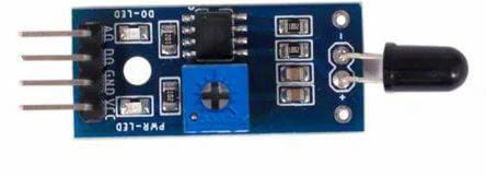
The Heat Flame Sensor is an electronic device designed to detect the presence of a flame or fire and convert this detection into an electrical signal. Manufactured by Robocraze, this sensor is commonly used in safety systems for gas appliances, fire detection systems, and in robotics for flame sensing capabilities.

Explore Projects Built with Heat Flame Sensor

Use Cirkit Designer to design, explore, and prototype these projects online. Some projects support real-time simulation. Click "Open Project" to start designing instantly!
Arduino UNO-Based Environmental Monitoring System with Wi-Fi Connectivity
Image of fire and smoke detection: A project utilizing Heat Flame Sensor in a practical application
This circuit is designed to monitor environmental conditions using a heat flame sensor and an MQ135 air quality sensor, display information on an LCD screen, and maintain accurate time with an RTC module. It includes an ESP8266 Wi-Fi module for potential wireless connectivity and uses a buzzer and LED for alerts or status indications. The Arduino UNO serves as the central controller, though the specific embedded code for operation is not yet provided.
Cirkit Designer LogoOpen Project in Cirkit Designer
Flame Detection and Automatic Water Pump Activation System
Image of FIRE: A project utilizing Heat Flame Sensor in a practical application
This circuit features a heat flame sensor that likely triggers a response when detecting heat or flame. The sensor's digital output (DO) is connected through a resistor to a TIP41C transistor, which acts as a switch for a buzzer and a water pump, indicating that the circuit is designed to sound an alarm and possibly activate a water pump in the event of detecting a flame. The 9V battery powers the circuit, and all components share a common ground.
Cirkit Designer LogoOpen Project in Cirkit Designer
Arduino UNO Based Gas and Flame Detection System with I2C LCD Feedback and Alert Buzzer
Image of SCHEMATIC DIAGRAM PROJECT 2: A project utilizing Heat Flame Sensor in a practical application
This circuit features an Arduino UNO microcontroller connected to a heat flame sensor and an MQ-2 gas sensor for detecting flames and gases, respectively. The Arduino is also interfaced with an I2C LCD 16x2 screen for displaying sensor readings or status messages. Additionally, there is a buzzer connected to the Arduino, which can be used for audible alerts or alarms based on sensor inputs.
Cirkit Designer LogoOpen Project in Cirkit Designer
Arduino UNO Based Multi-Flame Sensor Detection System
Image of flame sensor: A project utilizing Heat Flame Sensor in a practical application
This circuit is designed to monitor for the presence of flames using three flame sensors connected to an Arduino UNO. Each flame sensor's analog output is connected to a separate analog input on the Arduino, allowing the microcontroller to read the intensity of the flame detected by each sensor. The 5V and GND pins of the Arduino provide power to the flame sensors.
Cirkit Designer LogoOpen Project in Cirkit Designer

Explore Projects Built with Heat Flame Sensor

Use Cirkit Designer to design, explore, and prototype these projects online. Some projects support real-time simulation. Click "Open Project" to start designing instantly!
Image of fire and smoke detection: A project utilizing Heat Flame Sensor in a practical application
Arduino UNO-Based Environmental Monitoring System with Wi-Fi Connectivity
This circuit is designed to monitor environmental conditions using a heat flame sensor and an MQ135 air quality sensor, display information on an LCD screen, and maintain accurate time with an RTC module. It includes an ESP8266 Wi-Fi module for potential wireless connectivity and uses a buzzer and LED for alerts or status indications. The Arduino UNO serves as the central controller, though the specific embedded code for operation is not yet provided.
Cirkit Designer LogoOpen Project in Cirkit Designer
Image of FIRE: A project utilizing Heat Flame Sensor in a practical application
Flame Detection and Automatic Water Pump Activation System
This circuit features a heat flame sensor that likely triggers a response when detecting heat or flame. The sensor's digital output (DO) is connected through a resistor to a TIP41C transistor, which acts as a switch for a buzzer and a water pump, indicating that the circuit is designed to sound an alarm and possibly activate a water pump in the event of detecting a flame. The 9V battery powers the circuit, and all components share a common ground.
Cirkit Designer LogoOpen Project in Cirkit Designer
Image of SCHEMATIC DIAGRAM PROJECT 2: A project utilizing Heat Flame Sensor in a practical application
Arduino UNO Based Gas and Flame Detection System with I2C LCD Feedback and Alert Buzzer
This circuit features an Arduino UNO microcontroller connected to a heat flame sensor and an MQ-2 gas sensor for detecting flames and gases, respectively. The Arduino is also interfaced with an I2C LCD 16x2 screen for displaying sensor readings or status messages. Additionally, there is a buzzer connected to the Arduino, which can be used for audible alerts or alarms based on sensor inputs.
Cirkit Designer LogoOpen Project in Cirkit Designer
Image of flame sensor: A project utilizing Heat Flame Sensor in a practical application
Arduino UNO Based Multi-Flame Sensor Detection System
This circuit is designed to monitor for the presence of flames using three flame sensors connected to an Arduino UNO. Each flame sensor's analog output is connected to a separate analog input on the Arduino, allowing the microcontroller to read the intensity of the flame detected by each sensor. The 5V and GND pins of the Arduino provide power to the flame sensors.
Cirkit Designer LogoOpen Project in Cirkit Designer

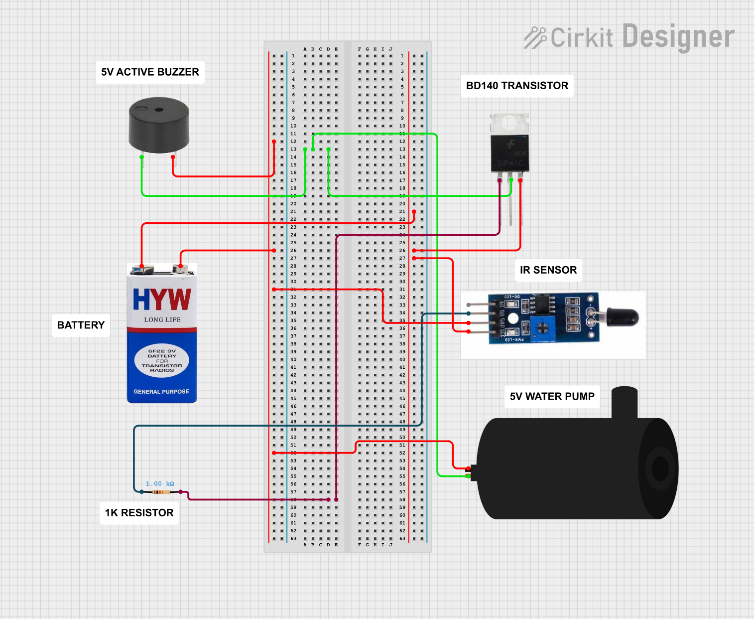
Common Applications and Use Cases

  • Gas stove safety systems to ensure the flame is lit
  • Fire alarms and fire-fighting robots
  • Environmental monitoring for fire detection

Technical Specifications

Key Technical Details

  • Operating Voltage: 3.3V to 5V DC
  • Output Type: Digital signal (0V or 5V)
  • Detection Range: Up to 1 meter (for a standard flame)
  • Response Time: < 1 second
  • Operating Temperature: -25°C to 85°C

Pin Configuration and Descriptions

Pin Number Pin Name Description
1 VCC Power supply (3.3V to 5V DC)
2 GND Ground
3 DO Digital output; connects to a digital pin
4 AO Analog output; connects to an analog pin

Usage Instructions

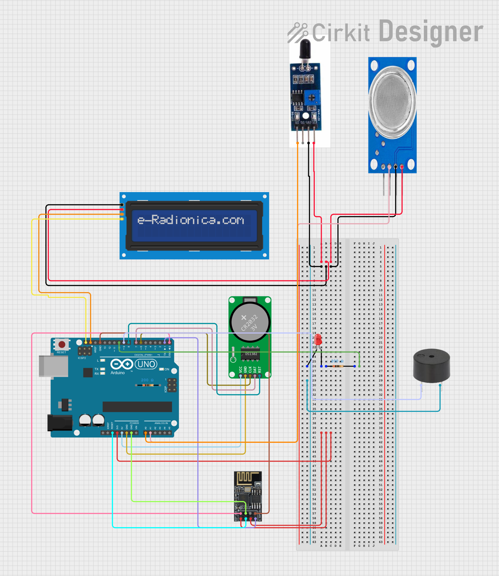
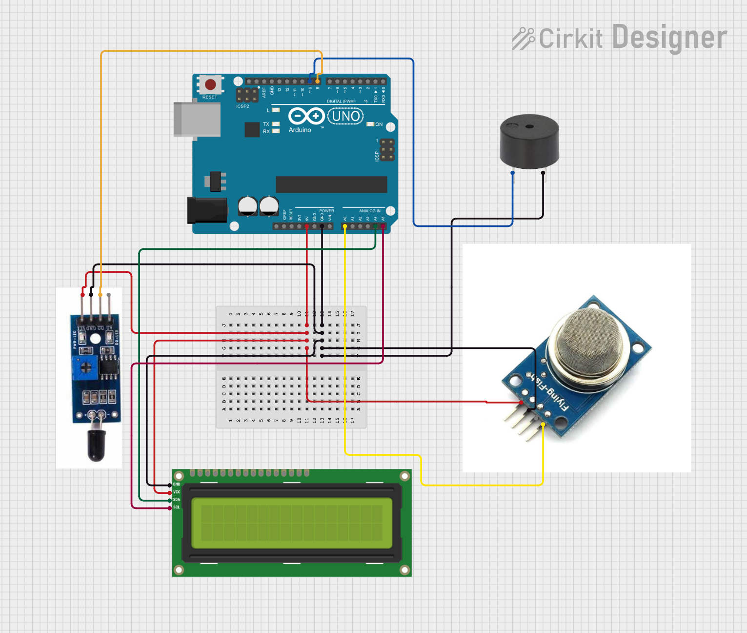
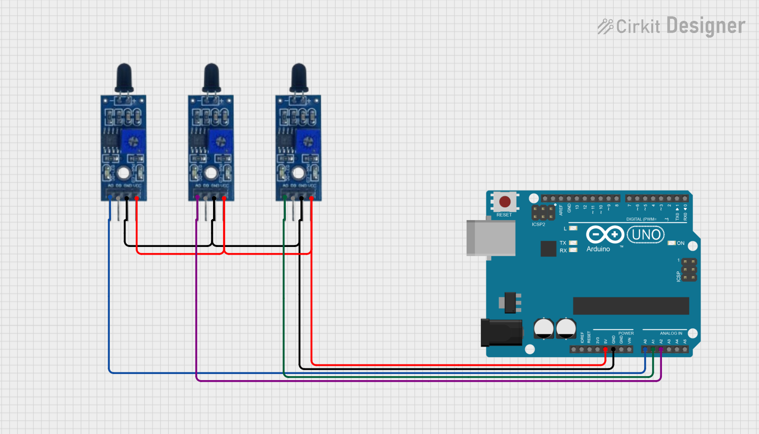
How to Use the Component in a Circuit

  1. Connect the VCC pin to a 3.3V or 5V power supply.
  2. Connect the GND pin to the ground of the power supply.
  3. Connect the DO (Digital Output) pin to a digital input pin on a microcontroller if you want to use the digital signal.
  4. Optionally, connect the AO (Analog Output) pin to an analog input pin on a microcontroller if you want to measure the intensity of the flame.

Important Considerations and Best Practices

  • Ensure that the sensor is placed in a location where it can detect the flame without being damaged by heat.
  • Avoid placing the sensor in an environment with strong air flow as it may affect the detection accuracy.
  • Use a pull-up or pull-down resistor with the digital output if required by your microcontroller.

Example Code for Arduino UNO

// Define the digital pin connected to the sensor's DO pin
const int flameSensorPin = 2;

void setup() {
  pinMode(flameSensorPin, INPUT); // Set the flame sensor pin as an input
  Serial.begin(9600);             // Start serial communication at 9600 baud
}

void loop() {
  int flameDetected = digitalRead(flameSensorPin); // Read the digital signal
  if (flameDetected == LOW) {                      // Check if a flame is detected
    Serial.println("Flame detected!");
  } else {
    Serial.println("No flame detected.");
  }
  delay(1000); // Wait for 1 second before the next read
}

Troubleshooting and FAQs

Common Issues Users Might Face

  • False Alarms: Adjust the sensor's sensitivity or reposition it to avoid false alarms.
  • No Response: Check the connections and ensure the power supply is within the specified range.

Solutions and Tips for Troubleshooting

  • If the sensor is not detecting a flame, ensure that it is not facing any strong light sources that could interfere with detection.
  • In case of erratic readings, check for any loose connections and ensure that the sensor is not exposed to sudden temperature changes.

FAQs

Q: Can the sensor detect different types of flames? A: Yes, the sensor can detect various types of flames, but its sensitivity may vary depending on the flame's characteristics.

Q: Is it possible to adjust the sensitivity of the sensor? A: Some models come with a potentiometer for sensitivity adjustment. Refer to the specific model's datasheet for details.

Q: How far can the sensor detect a flame? A: The standard detection range is up to 1 meter for a typical flame, but this can vary based on the size and intensity of the flame.

Q: Can the sensor be used outdoors? A: While the sensor can be used outdoors, it should be protected from the elements and extreme temperatures to ensure accurate operation.

Q: What is the difference between the AO and DO pins? A: The AO pin provides an analog output that varies with the intensity of the flame, while the DO pin provides a digital output that indicates the presence or absence of a flame.

For further assistance or technical support, please contact Robocraze customer service with the part ID olwe54jugd5r.