How to Use ELG-150-12DA: Examples, Pinouts, and Specs
Introduction
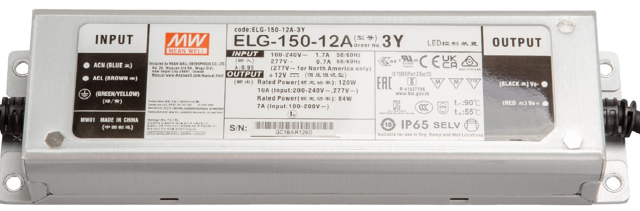
The ELG-150-12DA is a 150W LED driver designed to provide a stable 12V DC output for powering LED lighting systems. This high-performance driver is known for its compact design, high efficiency, and robust build quality. It is suitable for both indoor and outdoor applications, thanks to its IP67-rated enclosure and comprehensive protection features, including over-voltage, over-current, and short-circuit safeguards.
Explore Projects Built with ELG-150-12DA


Explore Projects Built with ELG-150-12DA
Common Applications and Use Cases
- LED strip lighting for residential and commercial spaces
- Outdoor LED lighting systems, such as streetlights and signage
- Industrial lighting applications requiring high reliability
- Architectural lighting installations
- Any 12V DC-powered LED system requiring a constant voltage source
Technical Specifications
The ELG-150-12DA is engineered to meet the demands of modern LED lighting systems. Below are its key technical specifications:
| Parameter | Value |
|---|---|
| Output Voltage | 12V DC |
| Output Current | 0–12.5A |
| Output Power | 150W |
| Input Voltage Range | 100–305V AC |
| Efficiency | Up to 91% |
| Power Factor | ≥ 0.95 (at full load, 230V AC) |
| Operating Temperature | -40°C to +85°C (case temperature) |
| Enclosure Rating | IP67 (dust-tight and waterproof) |
| Dimming Control | 3-in-1 dimming (0–10V, PWM, Resistor) |
| Protections | Over-voltage, over-current, short-circuit |
| Dimensions | 220mm x 68mm x 38.8mm |
| Weight | 0.9 kg |
Pin Configuration and Descriptions
The ELG-150-12DA has input and output wiring for AC and DC connections, as well as dimming control. Below is the pin configuration:
Input and Output Connections
| Wire Color | Function | Description |
|---|---|---|
| Black | AC Line (L) | Connect to the live wire of the AC input |
| White | AC Neutral (N) | Connect to the neutral wire of the AC input |
| Green/Yellow | Ground (GND) | Connect to earth ground for safety |
| Red | DC Positive (+V) | Positive output for LED load |
| Black | DC Negative (-V) | Negative output for LED load |
Dimming Control Wires
| Wire Color | Function | Description |
|---|---|---|
| Blue | DIM- | Negative terminal for dimming control |
| White | DIM+ | Positive terminal for dimming control |
Usage Instructions
How to Use the ELG-150-12DA in a Circuit
- Input Connection: Connect the black (AC Line) and white (AC Neutral) wires to the AC power source. Ensure the input voltage is within the range of 100–305V AC.
- Output Connection: Connect the red (DC Positive) and black (DC Negative) wires to the LED load. Ensure the total load does not exceed 150W.
- Dimming Control (Optional):
- For 0–10V dimming, connect a 0–10V dimmer to the DIM+ (white) and DIM- (blue) wires.
- For PWM dimming, connect a PWM signal (frequency: 100–3kHz) to the DIM+ and DIM- wires.
- For resistive dimming, connect a variable resistor (100kΩ max) between DIM+ and DIM-.
- Grounding: Connect the green/yellow wire to earth ground for safety.
Important Considerations and Best Practices
- Load Matching: Ensure the total power of the connected LED load does not exceed 150W to avoid overloading the driver.
- Ventilation: Install the driver in a well-ventilated area to prevent overheating.
- Waterproofing: For outdoor use, ensure all connections are properly sealed to maintain the IP67 rating.
- Dimming Compatibility: Verify that the dimming control method (0–10V, PWM, or resistor) is compatible with your dimmer or control system.
- Polarity: Double-check the polarity of the DC output connections to avoid damaging the LED load.
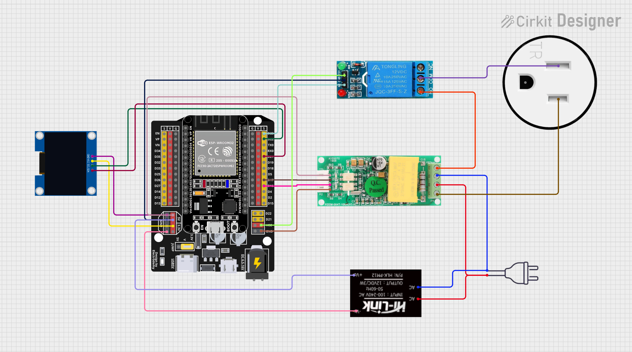
Example: Connecting to an Arduino UNO for PWM Dimming
The ELG-150-12DA can be dimmed using a PWM signal from an Arduino UNO. Below is an example setup and code:
Circuit Setup
- Connect the Arduino's GND pin to the DIM- (blue) wire of the driver.
- Connect a PWM-capable pin (e.g., pin 9) of the Arduino to the DIM+ (white) wire of the driver.
- Ensure the Arduino and the driver share a common ground.
Arduino Code
// Example code to control the ELG-150-12DA using PWM from an Arduino UNO

const int pwmPin = 9; // PWM-capable pin connected to DIM+ of the driver

void setup() {
  pinMode(pwmPin, OUTPUT); // Set the PWM pin as an output
}

void loop() {
  // Gradually increase brightness
  for (int brightness = 0; brightness <= 255; brightness++) {
    analogWrite(pwmPin, brightness); // Write PWM signal to DIM+
    delay(10); // Small delay for smooth dimming
  }

  // Gradually decrease brightness
  for (int brightness = 255; brightness >= 0; brightness--) {
    analogWrite(pwmPin, brightness); // Write PWM signal to DIM+
    delay(10); // Small delay for smooth dimming
  }
}
Troubleshooting and FAQs
Common Issues and Solutions
No Output Voltage
- Cause: Incorrect AC input wiring or no AC power.
- Solution: Verify the AC input connections and ensure the power source is active.
LEDs Flicker
- Cause: Incompatible dimming signal or unstable input voltage.
- Solution: Check the dimming control signal and ensure it matches the driver's specifications. Verify the input voltage is stable.
Driver Overheats
- Cause: Insufficient ventilation or excessive load.
- Solution: Ensure the driver is installed in a well-ventilated area and the load does not exceed 150W.
Dimming Does Not Work
- Cause: Incorrect dimming connections or incompatible dimmer.
- Solution: Verify the dimming wires are correctly connected and the dimmer is compatible with the driver's dimming methods.
FAQs
Can I use the ELG-150-12DA with a 24V LED load?
- No, the driver is designed for 12V LED loads only. Using a 24V load may damage the LEDs or the driver.
Is the driver suitable for outdoor use?
- Yes, the IP67 rating ensures the driver is dust-tight and waterproof, making it suitable for outdoor applications.
What happens if the load exceeds 150W?
- The driver includes over-current protection and will shut down to prevent damage. Reduce the load to within the specified limit.
Can I use a microcontroller other than Arduino for dimming?
- Yes, any microcontroller capable of generating a 0–10V, PWM, or resistive dimming signal can be used. Ensure compatibility with the driver's dimming specifications.