How to Use TB6600: Examples, Pinouts, and Specs
Introduction
The TB6600 is a high-performance microstepping driver designed for bipolar stepper motors. It is capable of driving motors with a current rating of up to 4.5A, making it suitable for demanding applications. The driver supports adjustable current control, multiple microstepping options, and includes built-in protection features such as overcurrent and overheating safeguards. These features make the TB6600 a popular choice for CNC machines, 3D printers, robotics, and other precision motion control systems.
Explore Projects Built with TB6600


Explore Projects Built with TB6600
Common Applications
- CNC machines for precise motion control
- 3D printers for accurate layer positioning
- Robotics for stepper motor actuation
- Automated machinery and conveyor systems
- DIY projects requiring stepper motor control
Technical Specifications
The TB6600 offers robust performance and flexibility for stepper motor control. Below are its key technical details:
Key Specifications
| Parameter | Value |
|---|---|
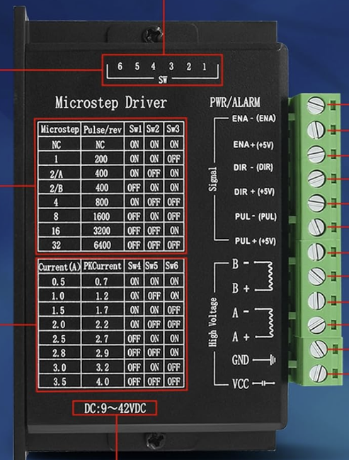
| Input Voltage Range | 9V to 42V DC |
| Maximum Output Current | 4.5A |
| Microstepping Options | Full, 1/2, 1/4, 1/8, 1/16 |
| Control Signal Voltage | 3.3V to 5V |
| Operating Temperature | -10°C to +45°C |
| Protection Features | Overcurrent, Overheating |
Pin Configuration and Descriptions
The TB6600 driver typically has the following pin configuration:
Input Pins
| Pin Name | Description |
|---|---|
| PUL+ | Pulse signal input (positive terminal) |
| PUL- | Pulse signal input (negative terminal) |
| DIR+ | Direction signal input (positive terminal) |
| DIR- | Direction signal input (negative terminal) |
| ENA+ | Enable signal input (positive terminal) (optional, used to enable/disable) |
| ENA- | Enable signal input (negative terminal) |
Output Pins
| Pin Name | Description |
|---|---|
| A+ | Stepper motor coil A positive terminal |
| A- | Stepper motor coil A negative terminal |
| B+ | Stepper motor coil B positive terminal |
| B- | Stepper motor coil B negative terminal |
Power Pins
| Pin Name | Description |
|---|---|
| VCC | Power supply input (9V to 42V DC) |
| GND | Ground connection |
Usage Instructions
How to Use the TB6600 in a Circuit
Connect the Power Supply:
- Connect a DC power supply (9V to 42V) to the VCC and GND pins of the TB6600.
- Ensure the power supply can provide sufficient current for the stepper motor.
Connect the Stepper Motor:
- Connect the stepper motor's coil wires to the A+, A-, B+, and B- output pins.
- Refer to the motor's datasheet to identify the correct coil pairs.
Connect Control Signals:
- Connect the PUL+, DIR+, and ENA+ pins to the control signals from a microcontroller (e.g., Arduino).
- Connect the PUL-, DIR-, and ENA- pins to the ground of the microcontroller.
Set Microstepping and Current:
- Use the DIP switches on the TB6600 to configure the desired microstepping mode and current limit.
- Refer to the TB6600 datasheet for the DIP switch settings.
Test the Setup:
- Power on the system and send pulse and direction signals from the microcontroller to control the motor.
Important Considerations
- Heat Dissipation: The TB6600 can generate significant heat during operation. Use a heatsink or active cooling to prevent overheating.
- Current Settings: Set the current limit to match the stepper motor's rated current to avoid damage.
- Signal Voltage: Ensure the control signals from the microcontroller are within the 3.3V to 5V range.
Example: Using the TB6600 with Arduino UNO
Below is an example Arduino sketch to control a stepper motor using the TB6600:
// Define control pins for the TB6600
const int pulsePin = 3;  // Pin connected to PUL+ on TB6600
const int dirPin = 4;    // Pin connected to DIR+ on TB6600
const int enablePin = 5; // Pin connected to ENA+ on TB6600

void setup() {
  // Set control pins as outputs
  pinMode(pulsePin, OUTPUT);
  pinMode(dirPin, OUTPUT);
  pinMode(enablePin, OUTPUT);

  // Enable the driver
  digitalWrite(enablePin, LOW); // LOW enables the driver
}

void loop() {
  // Set direction
  digitalWrite(dirPin, HIGH); // HIGH for one direction, LOW for the other

  // Generate pulses to move the motor
  for (int i = 0; i < 200; i++) { // 200 steps for one revolution (example)
    digitalWrite(pulsePin, HIGH); // Send a HIGH pulse
    delayMicroseconds(500);       // Pulse duration (adjust for speed)
    digitalWrite(pulsePin, LOW);  // Send a LOW pulse
    delayMicroseconds(500);       // Delay between pulses
  }

  delay(1000); // Wait 1 second before reversing direction

  // Reverse direction
  digitalWrite(dirPin, LOW);
  for (int i = 0; i < 200; i++) {
    digitalWrite(pulsePin, HIGH);
    delayMicroseconds(500);
    digitalWrite(pulsePin, LOW);
    delayMicroseconds(500);
  }

  delay(1000); // Wait 1 second before repeating
}
Troubleshooting and FAQs
Common Issues and Solutions
Motor Not Moving:
- Cause: Incorrect wiring or insufficient power supply.
- Solution: Double-check all connections and ensure the power supply meets the voltage and current requirements.
Motor Vibrates but Does Not Rotate:
- Cause: Incorrect coil wiring.
- Solution: Verify the stepper motor's coil pairs and ensure they are connected correctly to the A+/A- and B+/B- pins.
Driver Overheating:
- Cause: Excessive current or poor heat dissipation.
- Solution: Reduce the current setting using the DIP switches and add a heatsink or fan.
Stepper Motor Skipping Steps:
- Cause: Insufficient current or incorrect microstepping settings.
- Solution: Increase the current setting and verify the microstepping configuration.
No Response from the Driver:
- Cause: Control signals not reaching the driver.
- Solution: Check the microcontroller's output pins and ensure proper signal levels (3.3V to 5V).
FAQs
Q1: Can the TB6600 drive unipolar stepper motors?
A1: No, the TB6600 is designed for bipolar stepper motors only.
Q2: What is the maximum step frequency supported by the TB6600?
A2: The TB6600 supports a maximum step frequency of approximately 200 kHz.
Q3: Can I use the TB6600 with a 12V power supply?
A3: Yes, the TB6600 supports input voltages from 9V to 42V, so a 12V power supply is compatible.
Q4: How do I select the correct microstepping mode?
A4: Use the DIP switches on the TB6600 to configure the microstepping mode. Refer to the datasheet for the switch settings.
Q5: Is the ENA+ pin mandatory for operation?
A5: No, the ENA+ pin is optional. If not used, leave it unconnected or tied to the ground.