How to Use 4x4 Matrix Keypad (SIM TEST): Examples, Pinouts, and Specs
Introduction
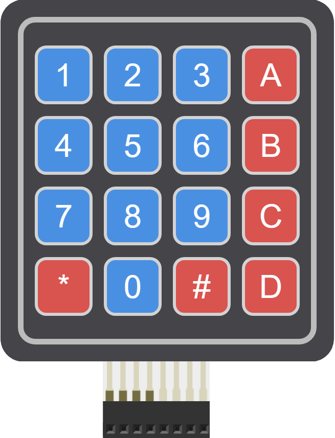
The 4x4 Matrix Keypad is a compact input device consisting of 16 keys arranged in a grid format. This design allows for efficient user input, making it ideal for various electronic projects. Common applications include data entry, control systems, and particularly in SIM testing where numeric input is essential. The keypad's versatility makes it a popular choice among hobbyists and professionals alike.
Explore Projects Built with 4x4 Matrix Keypad (SIM TEST)
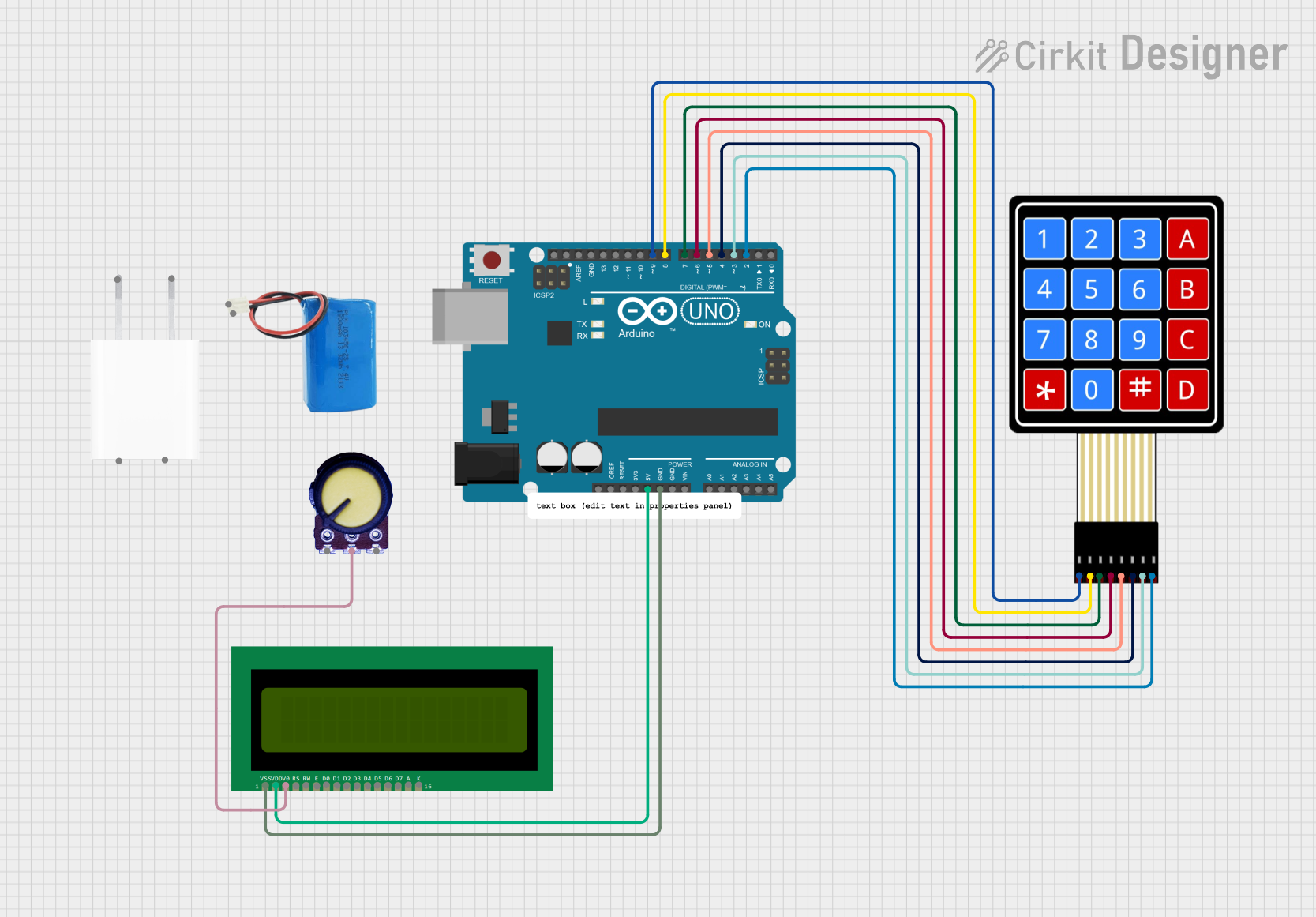
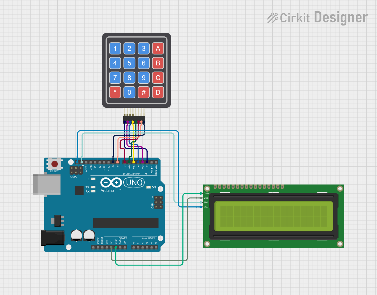
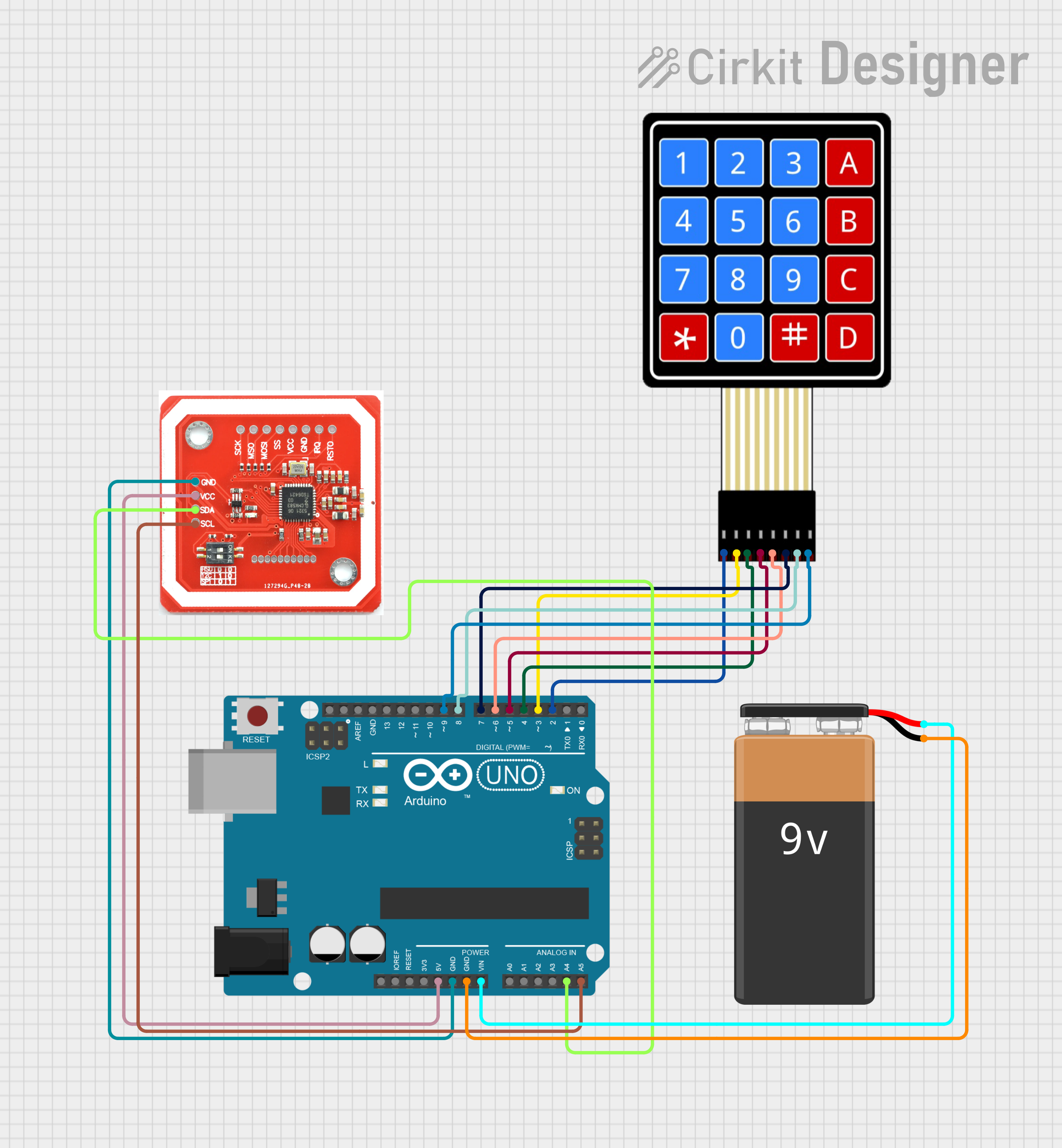
Explore Projects Built with 4x4 Matrix Keypad (SIM TEST)
Technical Specifications
Key Technical Details
| Specification | Value |
|---|---|
| Number of Keys | 16 |
| Voltage Rating | 3.3V to 5V |
| Current Rating | 20 mA (max per key) |
| Keypad Type | Matrix (4x4) |
| Dimensions | 4.0 cm x 4.0 cm |
Pin Configuration
The 4x4 Matrix Keypad typically has 8 pins, which are used to connect the rows and columns of the keypad. Below is the pin configuration:
| Pin Number | Pin Name | Description |
|---|---|---|
| 1 | R1 | Row 1 (connected to first row) |
| 2 | R2 | Row 2 (connected to second row) |
| 3 | R3 | Row 3 (connected to third row) |
| 4 | R4 | Row 4 (connected to fourth row) |
| 5 | C1 | Column 1 (connected to first column) |
| 6 | C2 | Column 2 (connected to second column) |
| 7 | C3 | Column 3 (connected to third column) |
| 8 | C4 | Column 4 (connected to fourth column) |
Usage Instructions
How to Use the Component in a Circuit
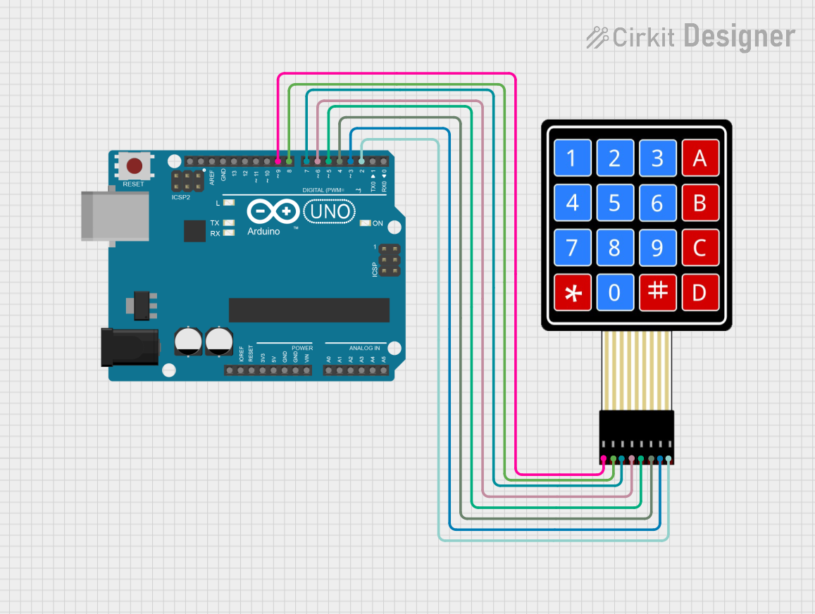
Wiring the Keypad:
- Connect the pins of the keypad to the digital pins of your microcontroller (e.g., Arduino UNO).
- Ensure that the rows (R1-R4) and columns (C1-C4) are connected correctly.
Sample Circuit:
- Connect R1 to pin 2, R2 to pin 3, R3 to pin 4, R4 to pin 5.
- Connect C1 to pin 6, C2 to pin 7, C3 to pin 8, C4 to pin 9.
Code Implementation:
- Use the
Keypadlibrary for easy handling of the keypad input.
- Use the
Important Considerations and Best Practices
- Debouncing: Implement debouncing in your code to avoid multiple readings from a single key press.
- Pull-up Resistors: Use internal pull-up resistors if available, or external resistors to ensure stable readings.
- Testing: Test the keypad with a simple sketch before integrating it into larger projects to ensure proper functionality.
Troubleshooting and FAQs
Common Issues Users Might Face
Key Not Responding:
- Ensure the keypad is wired correctly.
- Check for any loose connections.
Multiple Key Presses Detected:
- Implement debouncing in your code.
- Check for any short circuits between the pins.
Incorrect Key Readings:
- Verify that the correct pins are assigned in your code.
- Ensure that the keypad is functioning properly by testing with a multimeter.
Solutions and Tips for Troubleshooting
- Check Connections: Always double-check your wiring against the pin configuration.
- Use Serial Monitor: Utilize the Serial Monitor in the Arduino IDE to debug key presses.
- Library Documentation: Refer to the
Keypadlibrary documentation for additional functions and examples.
Sample Arduino Code
Here is a simple example of how to read input from the 4x4 Matrix Keypad using Arduino:
#include <Keypad.h>

// Define the keypad layout
const byte ROWS = 4; // Four rows
const byte COLS = 4; // Four columns
char keys[ROWS][COLS] = {
  {'1', '2', '3', 'A'},
  {'4', '5', '6', 'B'},
  {'7', '8', '9', 'C'},
  {'*', '0', '#', 'D'}
};

// Connect the row and column pins to Arduino
byte rowPins[ROWS] = {2, 3, 4, 5}; // Connect to the row pins
byte colPins[COLS] = {6, 7, 8, 9}; // Connect to the column pins

// Create an instance of the Keypad class
Keypad keypad = Keypad(makeKeymap(keys), rowPins, colPins, ROWS, COLS);

void setup() {
  Serial.begin(9600); // Start serial communication
}

void loop() {
  char key = keypad.getKey(); // Get the key pressed
  if (key) { // If a key is pressed
    Serial.println(key); // Print the key to the Serial Monitor
  }
}
This code initializes the keypad and prints the pressed key to the Serial Monitor. Make sure to adjust the pin numbers according to your wiring setup.