
How to Use TP4056: Examples, Pinouts, and Specs
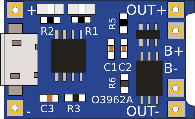
 Design with TP4056 in Cirkit Designer
Introduction
The TP4056 is a lithium-ion battery charger IC that provides a constant current/constant voltage (CC/CV) charging profile. It is specifically designed for charging single-cell lithium-ion batteries with high efficiency and reliability. The IC integrates several safety features, including thermal regulation, over-voltage protection, and automatic charge termination, making it a popular choice for portable electronics and DIY projects.
Explore Projects Built with TP4056
 Open Project in Cirkit Designer
 Open Project in Cirkit Designer
 Open Project in Cirkit Designer
 Open Project in Cirkit Designer
Explore Projects Built with TP4056
Open Project in Cirkit DesignerOpen Project in Cirkit DesignerOpen Project in Cirkit DesignerOpen Project in Cirkit DesignerCommon Applications and Use Cases
- Charging single-cell lithium-ion or lithium-polymer batteries
- Power banks and portable chargers
- Wearable devices
- DIY electronics projects
- Battery-powered IoT devices
Technical Specifications
The TP4056 is a compact and efficient charging IC with the following key specifications:
| Parameter | Value |
|---|---|
| Input Voltage Range | 4.0V to 8.0V |
| Charging Voltage | 4.2V ± 1% |
| Maximum Charging Current | 1A (adjustable via external resistor) |
| Charging Method | Constant Current / Constant Voltage (CC/CV) |
| Operating Temperature Range | -40°C to +85°C |
| Standby Current | < 55µA |
| Battery Overvoltage Protection | 4.3V |
| Thermal Regulation | 120°C (reduces charging current to prevent overheating) |
Pin Configuration and Descriptions
The TP4056 is typically available in an 8-pin SOP package. Below is the pin configuration and description:
| Pin Name | Pin Number | Description |
|---|---|---|
| BAT | 1 | Battery connection pin. Connect directly to the positive terminal of the battery. |
| GND | 2 | Ground pin. Connect to the system ground. |
| VCC | 3 | Input voltage pin. Connect to a DC supply (4.0V to 8.0V). |
| PROG | 4 | Charging current programming pin. Connect a resistor to set the charging current. |
| TEMP | 5 | Temperature monitoring pin. Connect to an NTC thermistor for battery temperature sensing. |
| STAT1 | 6 | Status indicator pin 1. Used with STAT2 to indicate charging status. |
| STAT2 | 7 | Status indicator pin 2. Used with STAT1 to indicate charging status. |
| CE | 8 | Chip enable pin. Pull low to enable charging, pull high to disable. |
Usage Instructions
How to Use the TP4056 in a Circuit
- Power Supply: Connect a DC power source (4.0V to 8.0V) to the VCC pin. Ensure the power source can supply sufficient current for the charging process.
- Battery Connection: Connect the positive terminal of the lithium-ion battery to the BAT pin and the negative terminal to GND.
- Set Charging Current: Use a resistor (RPROG) between the PROG pin and GND to set the desired charging current. The charging current can be calculated using the formula: [ I_{CHG} = \frac{1200}{R_{PROG}} ] For example, a 1.2kΩ resistor sets the charging current to 1A.
- Status Indicators: Connect LEDs to the STAT1 and STAT2 pins (with appropriate current-limiting resistors) to monitor the charging status:
- STAT1 ON, STAT2 OFF: Charging in progress.
- STAT1 OFF, STAT2 ON: Charging complete.
- Both OFF: No battery connected or charging disabled.
- Temperature Monitoring (Optional): Connect an NTC thermistor to the TEMP pin for battery temperature monitoring. If unused, connect TEMP to GND.
Important Considerations and Best Practices
- Thermal Management: Ensure proper heat dissipation, especially when charging at high currents. Use a heat sink or place the IC on a PCB with good thermal conductivity.
- Input Voltage: Avoid exceeding the maximum input voltage of 8.0V to prevent damage to the IC.
- Battery Protection: Use a protection circuit module (PCM) with the battery to prevent over-discharge and over-current conditions.
- Capacitors: Place a 1µF ceramic capacitor close to the VCC pin and a 10µF capacitor near the BAT pin for stable operation.
Example: Using TP4056 with Arduino UNO
The TP4056 can be used with an Arduino UNO to monitor the charging status. Below is an example code to read the status pins:
// TP4056 Status Monitoring with Arduino UNO
// Connect STAT1 to Arduino pin 2 and STAT2 to pin 3

const int stat1Pin = 2; // STAT1 pin connected to Arduino digital pin 2
const int stat2Pin = 3; // STAT2 pin connected to Arduino digital pin 3

void setup() {
  pinMode(stat1Pin, INPUT); // Set STAT1 as input
  pinMode(stat2Pin, INPUT); // Set STAT2 as input
  Serial.begin(9600);       // Initialize serial communication
}

void loop() {
  int stat1 = digitalRead(stat1Pin); // Read STAT1 pin
  int stat2 = digitalRead(stat2Pin); // Read STAT2 pin

  if (stat1 == HIGH && stat2 == LOW) {
    Serial.println("Charging in progress...");
  } else if (stat1 == LOW && stat2 == HIGH) {
    Serial.println("Charging complete.");
  } else if (stat1 == LOW && stat2 == LOW) {
    Serial.println("No battery connected or charging disabled.");
  } else {
    Serial.println("Unknown status.");
  }

  delay(1000); // Wait for 1 second before checking again
}
Troubleshooting and FAQs
Common Issues and Solutions
Battery Not Charging
- Cause: Incorrect input voltage or insufficient current supply.
- Solution: Verify the input voltage is between 4.0V and 8.0V and the power source can supply enough current.
Overheating
- Cause: High charging current or poor thermal dissipation.
- Solution: Reduce the charging current by increasing the RPROG resistor value or improve heat dissipation.
Status LEDs Not Working
- Cause: Incorrect LED connections or missing current-limiting resistors.
- Solution: Check the LED connections and ensure resistors are used to limit current.
Charging Stops Prematurely
- Cause: Battery temperature out of range or faulty battery.
- Solution: Verify the battery temperature is within the safe range and replace the battery if necessary.
FAQs
Q1: Can the TP4056 charge multiple batteries in series?
A1: No, the TP4056 is designed for single-cell lithium-ion batteries only. Charging multiple cells in series requires a specialized multi-cell charger.
Q2: How do I adjust the charging current?
A2: Use a resistor (RPROG) connected to the PROG pin. The charging current is calculated as ( I_{CHG} = \frac{1200}{R_{PROG}} ).
Q3: Is the TP4056 safe for unattended charging?
A3: Yes, the TP4056 includes safety features like thermal regulation and over-voltage protection. However, it is recommended to use a battery with a protection circuit for added safety.
Q4: Can I disable charging temporarily?
A4: Yes, pull the CE pin high to disable charging. Pull it low to enable charging.