How to Use LM324: Examples, Pinouts, and Specs
Introduction
The LM324 is a quad operational amplifier (op-amp) that integrates four independent, high-gain, frequency-compensated op-amps into a single package. It is designed to operate from a single power supply over a wide range of voltages, making it highly versatile for various analog applications. The LM324 is widely used in signal conditioning, filtering, amplification, and other analog signal processing tasks. Its low power consumption and cost-effectiveness make it a popular choice in both hobbyist and professional electronics projects.
Explore Projects Built with LM324
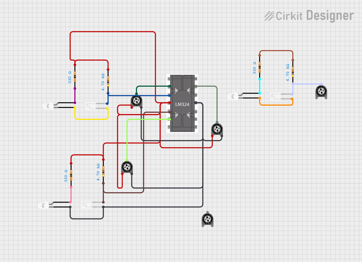
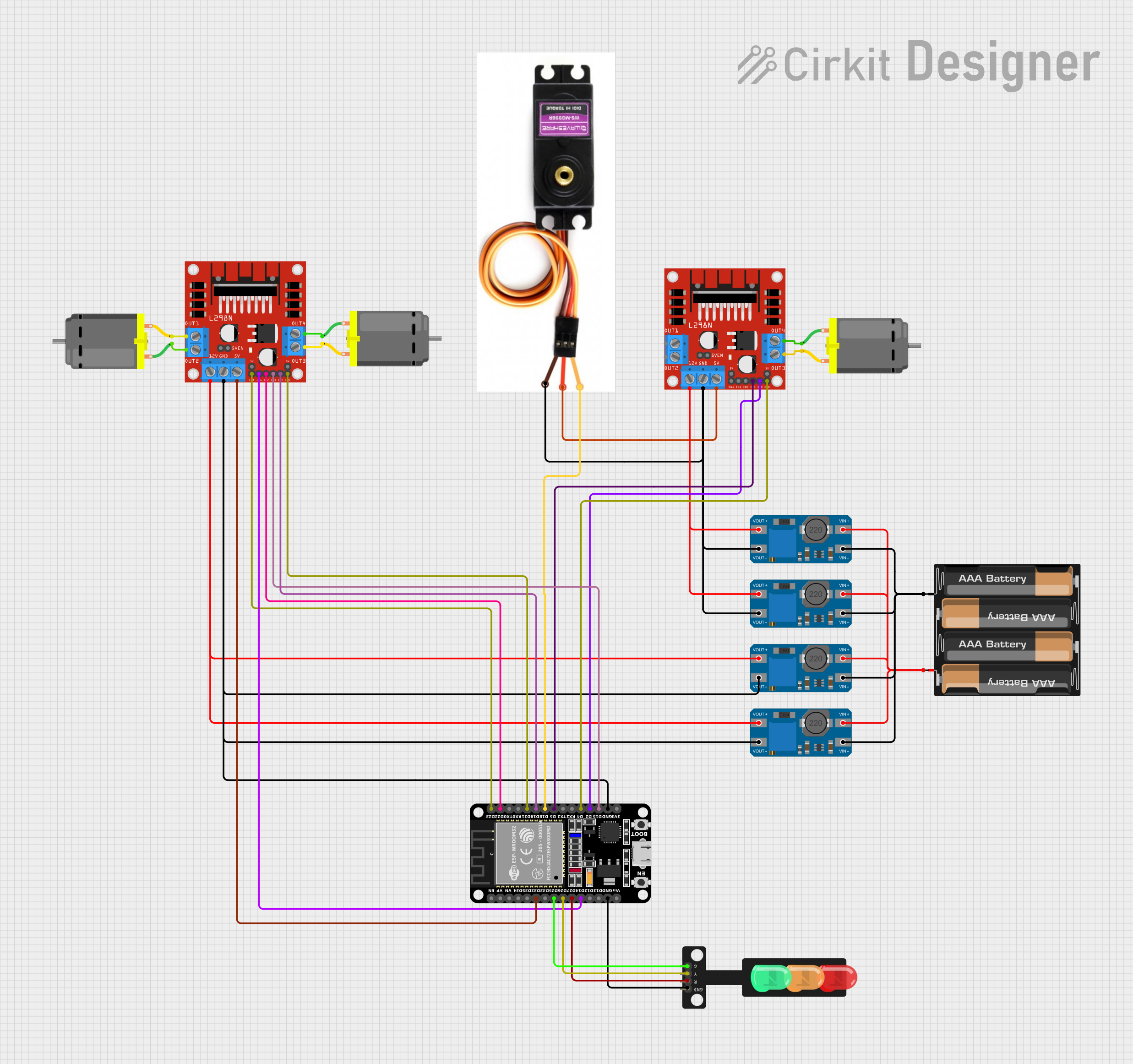


Explore Projects Built with LM324
Common Applications
- Signal amplification
- Active filters
- Voltage comparators
- Oscillators
- Analog computation circuits
- Sensor signal conditioning
Technical Specifications
The LM324 is available in multiple package types, such as DIP-14, SOIC-14, and TSSOP-14. Below are the key technical specifications:
| Parameter | Value |
|---|---|
| Supply Voltage (Vcc) | 3V to 32V (single supply) |
| Input Voltage Range | 0V to Vcc - 1.5V |
| Output Voltage Swing | 0V to Vcc - 1.5V (typical) |
| Input Offset Voltage | 2mV (typical) |
| Input Bias Current | 20nA (typical) |
| Gain Bandwidth Product | 1 MHz |
| Slew Rate | 0.5 V/µs |
| Operating Temperature Range | -40°C to +85°C |
| Quiescent Current (per op-amp) | 0.7 mA (typical) |
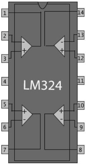
Pin Configuration
The LM324 is a 14-pin IC. The pinout and descriptions are as follows:
| Pin Number | Pin Name | Description |
|---|---|---|
| 1 | Output 1 | Output of Op-Amp 1 |
| 2 | Inverting Input 1 | Inverting input of Op-Amp 1 |
| 3 | Non-Inverting Input 1 | Non-inverting input of Op-Amp 1 |
| 4 | Vcc | Positive power supply |
| 5 | Non-Inverting Input 2 | Non-inverting input of Op-Amp 2 |
| 6 | Inverting Input 2 | Inverting input of Op-Amp 2 |
| 7 | Output 2 | Output of Op-Amp 2 |
| 8 | Output 3 | Output of Op-Amp 3 |
| 9 | Inverting Input 3 | Inverting input of Op-Amp 3 |
| 10 | Non-Inverting Input 3 | Non-inverting input of Op-Amp 3 |
| 11 | GND | Ground (0V reference) |
| 12 | Non-Inverting Input 4 | Non-inverting input of Op-Amp 4 |
| 13 | Inverting Input 4 | Inverting input of Op-Amp 4 |
| 14 | Output 4 | Output of Op-Amp 4 |
Usage Instructions
How to Use the LM324 in a Circuit
- Power Supply: Connect the Vcc pin (Pin 4) to the positive supply voltage (3V to 32V) and the GND pin (Pin 11) to ground.
- Input Connections: Connect the signal to be amplified or processed to the non-inverting (or inverting) input pins of the desired op-amp.
- Output Connections: The processed signal will be available at the corresponding output pin.
- Feedback Network: Use resistors, capacitors, or other components to configure the op-amp for the desired operation (e.g., amplification, filtering).
- Bypass Capacitor: Place a decoupling capacitor (e.g., 0.1 µF) close to the Vcc pin to reduce noise and improve stability.
Example: Using LM324 with Arduino UNO
The LM324 can be used to amplify an analog signal (e.g., from a sensor) before feeding it into the Arduino's analog input. Below is an example circuit and Arduino code for amplifying a signal.
Circuit Description
- Connect the sensor output to the non-inverting input of one of the op-amps (e.g., Pin 3).
- Use a resistor feedback network to set the gain.
- Connect the op-amp output (e.g., Pin 1) to the Arduino's analog input (e.g., A0).
Arduino Code
// LM324 Amplified Signal Reading Example
// Reads an amplified signal from the LM324 and displays it in the Serial Monitor.

const int analogPin = A0; // Analog pin connected to LM324 output

void setup() {
  Serial.begin(9600); // Initialize serial communication at 9600 baud
}

void loop() {
  int sensorValue = analogRead(analogPin); // Read the analog value
  float voltage = sensorValue * (5.0 / 1023.0); // Convert to voltage
  Serial.print("Amplified Signal Voltage: ");
  Serial.print(voltage);
  Serial.println(" V");
  delay(500); // Wait for 500ms before the next reading
}
Important Considerations
- Ensure the input voltage does not exceed the specified range (0V to Vcc - 1.5V).
- Use proper decoupling capacitors to minimize noise.
- Avoid driving heavy loads directly from the op-amp output; use a buffer if necessary.
- The LM324 is not suitable for high-speed applications due to its limited bandwidth and slew rate.
Troubleshooting and FAQs
Common Issues
No Output Signal:
- Check the power supply connections (Vcc and GND).
- Verify that the input signal is within the specified range.
- Ensure the feedback network is correctly configured.
Distorted Output:
- Verify that the output is not being driven beyond its voltage swing limits.
- Check for excessive noise or instability in the circuit.
High Power Consumption:
- Ensure that the circuit is not overloaded or shorted.
- Verify that the quiescent current matches the expected value.
FAQs
Q: Can the LM324 operate with a dual power supply?
A: Yes, the LM324 can operate with a dual power supply (e.g., ±15V). In this case, connect the positive supply to Vcc, the negative supply to GND, and the ground reference to the midpoint.
Q: What is the maximum gain I can achieve with the LM324?
A: The maximum gain depends on the feedback network and the bandwidth of the op-amp. For high gains, the bandwidth will decrease due to the gain-bandwidth product (1 MHz).
Q: Can I use the LM324 for audio applications?
A: The LM324 can be used for basic audio applications, but its limited bandwidth and slew rate may result in distortion for high-frequency signals.
Q: How do I protect the LM324 from damage?
A: Use proper decoupling capacitors, avoid exceeding the maximum voltage ratings, and ensure the input signals are within the specified range.