How to Use LILYGO XY_32_CAN+RS485: Examples, Pinouts, and Specs
Introduction
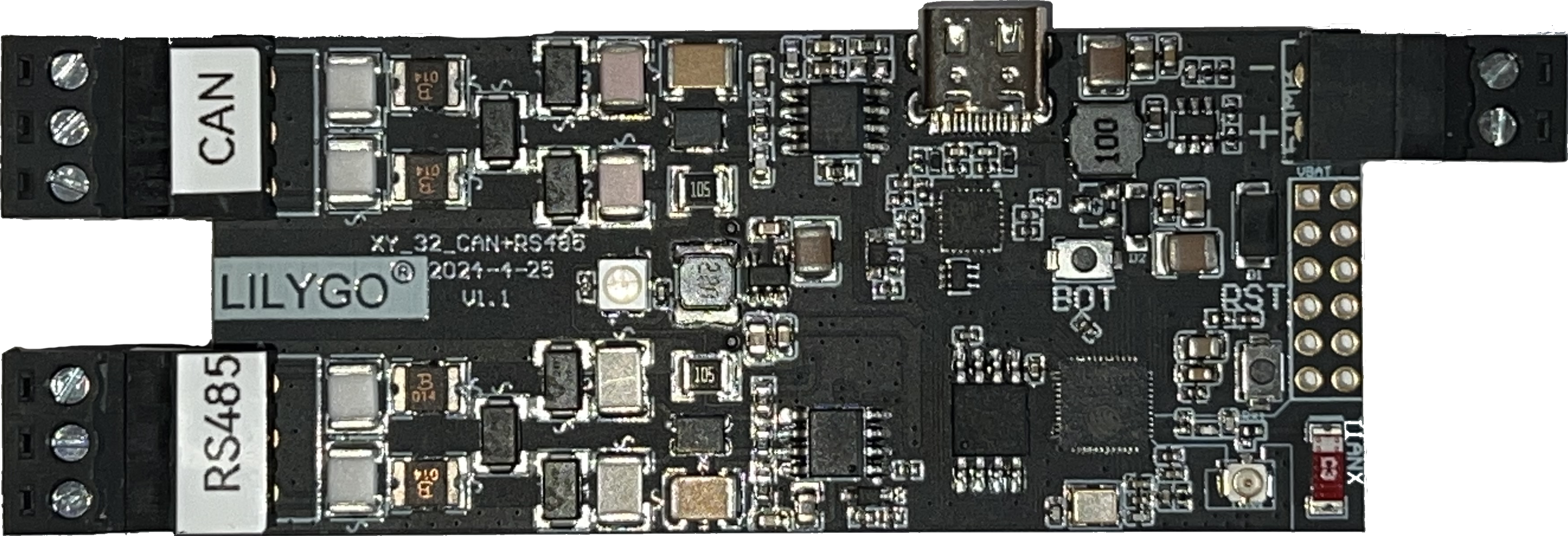
The LILYGO XY_32_CAN+RS485 V1.1 is a versatile microcontroller board designed for applications requiring robust communication protocols. It features both CAN (Controller Area Network) and RS485 interfaces, making it ideal for IoT (Internet of Things) applications, industrial automation, and other scenarios where reliable data transmission is critical. The board is based on the ESP32 microcontroller, which provides powerful processing capabilities, integrated Wi-Fi, and Bluetooth connectivity.
Explore Projects Built with LILYGO XY_32_CAN+RS485


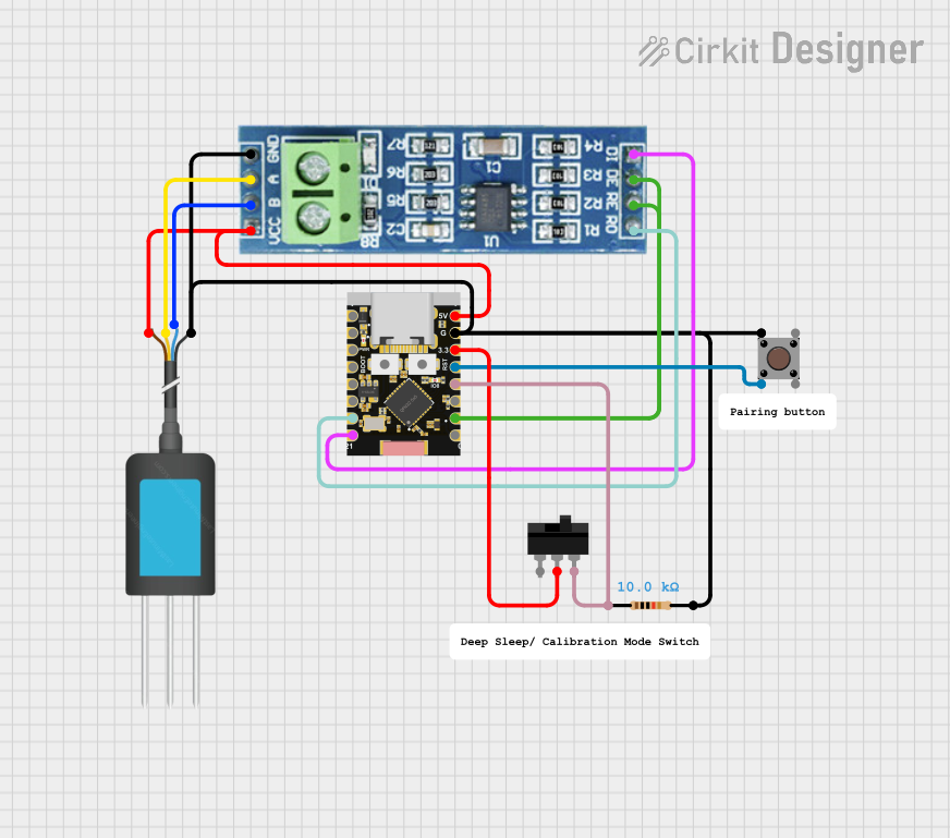
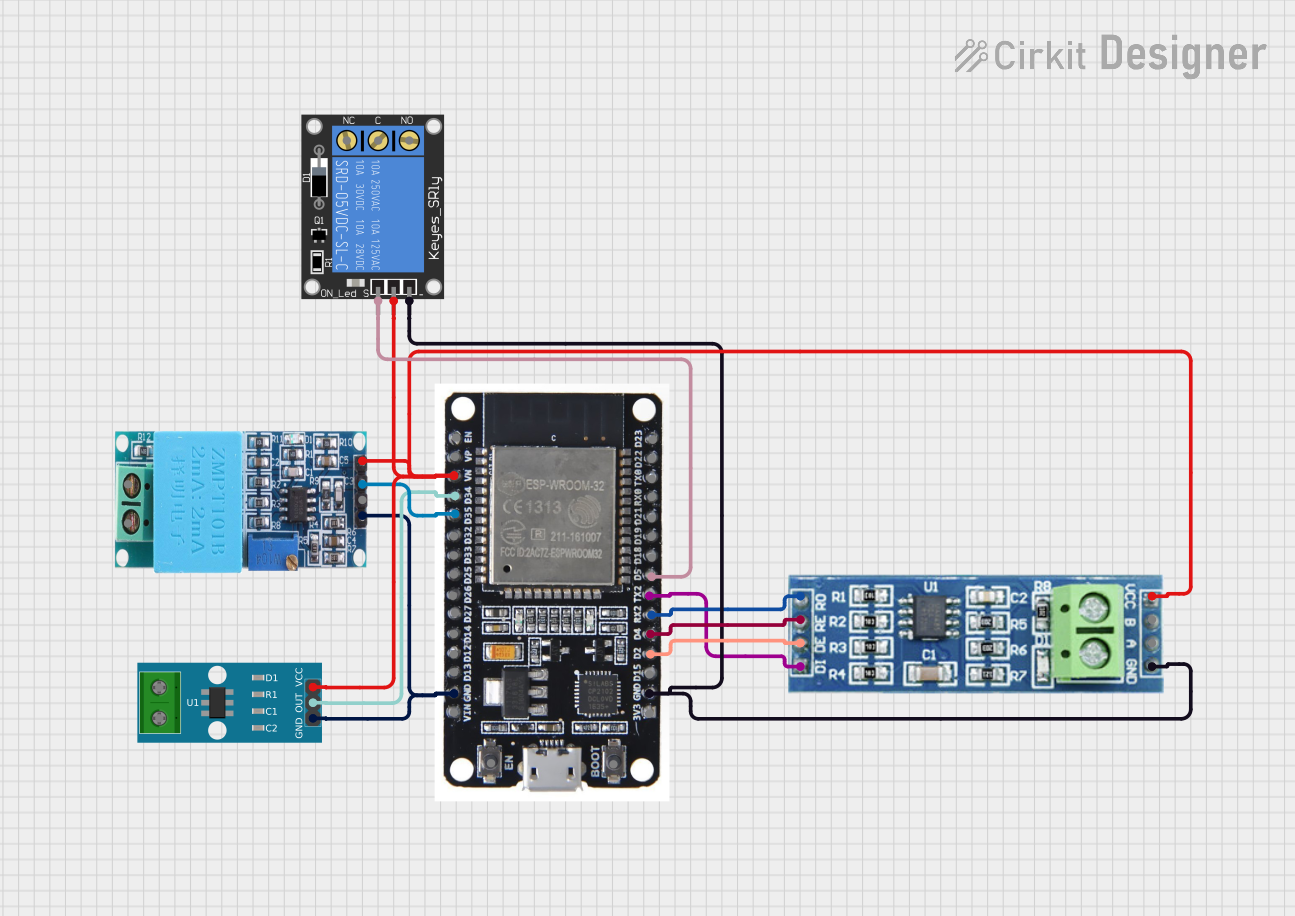
Explore Projects Built with LILYGO XY_32_CAN+RS485
Common Applications and Use Cases
- Industrial automation and control systems
- IoT devices requiring long-distance communication
- Vehicle communication networks (via CAN bus)
- Building management systems
- Data acquisition and monitoring systems
Technical Specifications
The LILYGO XY_32_CAN+RS485 V1.1 is equipped with the following key features and specifications:
General Specifications
| Parameter | Value |
|---|---|
| Microcontroller | ESP32 (dual-core, 240 MHz) |
| Communication Interfaces | CAN, RS485, Wi-Fi, Bluetooth |
| Operating Voltage | 3.3V |
| Input Voltage Range | 5V (via USB-C) |
| Flash Memory | 4MB |
| SRAM | 520KB |
| Dimensions | 56mm x 25mm |
Pin Configuration and Descriptions
The board features a variety of pins for communication, power, and general-purpose I/O. Below is the pinout description:
Power and Ground Pins
| Pin Name | Description |
|---|---|
| 3V3 | 3.3V output for external devices |
| GND | Ground |
| VIN | Input voltage (5V via USB-C) |
Communication Pins
| Pin Name | Description |
|---|---|
| CAN_TX | CAN bus transmit pin |
| CAN_RX | CAN bus receive pin |
| RS485_A | RS485 differential signal (A) |
| RS485_B | RS485 differential signal (B) |
General-Purpose I/O Pins
| Pin Name | Description |
|---|---|
| GPIOxx | General-purpose I/O pins |
| ADCxx | Analog-to-digital converter pins |
Usage Instructions
How to Use the Component in a Circuit
- Powering the Board: Connect the board to a 5V power source using the USB-C port. Ensure the power supply is stable to avoid damage.
- Connecting to CAN Bus:
- Use the
CAN_TXandCAN_RXpins to connect to the CAN bus. - Ensure proper termination resistors (typically 120Ω) are used at both ends of the CAN bus.
- Use the
- Connecting to RS485:
- Use the
RS485_AandRS485_Bpins to connect to the RS485 network. - Ensure the correct polarity of the differential signals.
- Use the
- Programming the Board:
- Use the Arduino IDE or ESP-IDF to program the ESP32 microcontroller.
- Install the necessary libraries for CAN and RS485 communication.
Important Considerations and Best Practices
- Voltage Levels: Ensure all connected devices operate at compatible voltage levels (3.3V logic).
- Termination Resistors: Always use proper termination resistors for CAN and RS485 networks to avoid signal reflections.
- ESD Protection: Use ESD protection devices if the board is deployed in environments prone to electrostatic discharge.
- Firmware Updates: Regularly update the firmware to ensure compatibility and security.
Example Code for Arduino UNO
Below is an example of how to use the LILYGO XY_32_CAN+RS485 V1.1 with the Arduino IDE for CAN communication:
#include <CAN.h> // Include the CAN library

void setup() {
  Serial.begin(115200); // Initialize serial communication for debugging
  while (!Serial);

  // Initialize CAN communication at 500 kbps
  if (!CAN.begin(500E3)) {
    Serial.println("Starting CAN failed!");
    while (1);
  }
  Serial.println("CAN initialized successfully.");
}

void loop() {
  // Send a CAN message
  CAN.beginPacket(0x123); // Set CAN ID
  CAN.write("Hello");     // Write data to the CAN bus
  CAN.endPacket();        // Send the packet

  delay(1000); // Wait for 1 second before sending the next message
}
Troubleshooting and FAQs
Common Issues and Solutions
The board does not power on:
- Ensure the USB-C cable is properly connected and the power source is functional.
- Verify that the input voltage is within the specified range (5V).
CAN communication is not working:
- Check the termination resistors on the CAN bus.
- Verify the baud rate settings in the code match the other devices on the CAN network.
- Ensure the
CAN_TXandCAN_RXpins are correctly connected.
RS485 communication issues:
- Verify the polarity of the
RS485_AandRS485_Bconnections. - Check for proper termination resistors on the RS485 network.
- Verify the polarity of the
Unable to upload code to the board:
- Ensure the correct board and port are selected in the Arduino IDE.
- Press the reset button on the board before uploading the code.
FAQs
Q: Can I use this board for Wi-Fi and Bluetooth applications?
A: Yes, the ESP32 microcontroller on the board supports both Wi-Fi and Bluetooth communication.
Q: What is the maximum baud rate for CAN and RS485?
A: The maximum baud rate for CAN is 1 Mbps, and for RS485, it depends on the network configuration but typically supports up to 10 Mbps.
Q: Is the board compatible with 5V logic devices?
A: No, the board operates at 3.3V logic levels. Use level shifters if interfacing with 5V devices.