Cirkit Designer Logo
Cirkit Designer
Your all-in-one circuit design IDE
Home / 
Component Documentation

How to Use SparkFun MAX6675 Thermocouple Breakout: Examples, Pinouts, and Specs

Image of SparkFun MAX6675 Thermocouple Breakout
Cirkit Designer LogoDesign with SparkFun MAX6675 Thermocouple Breakout in Cirkit Designer

Introduction

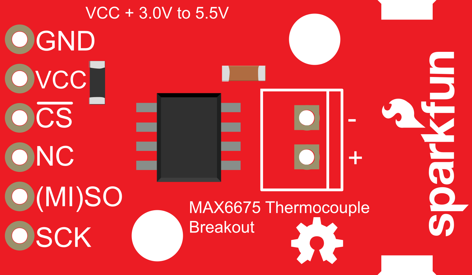
The SparkFun MAX6675 Thermocouple Breakout is an easy-to-use temperature sensing module that interfaces with a K-type thermocouple. It utilizes the MAX6675 chip to convert the thermocouple's output to a digital representation of temperature, which can be read using a simple SPI interface. This breakout is ideal for applications requiring high accuracy temperature measurements such as industrial controls, consumer products, and hobbyist projects.

Explore Projects Built with SparkFun MAX6675 Thermocouple Breakout

Use Cirkit Designer to design, explore, and prototype these projects online. Some projects support real-time simulation. Click "Open Project" to start designing instantly!
ESP8266 NodeMCU with MAX6675 Thermocouple Interface for Temperature Monitoring
Image of UAS Metrin: A project utilizing SparkFun MAX6675 Thermocouple Breakout in a practical application
This circuit is designed to measure temperature using a Type K thermocouple connected to a MAX6675 module, which digitizes the temperature reading. The MAX6675 module interfaces with an ESP8266 NodeMCU microcontroller over a SPI connection, using D5 (SCK), D6 (SO), and D8 (CS) for clock, data output, and chip select, respectively. The ESP8266 is responsible for processing the temperature data, which can then be used for monitoring, control, or communication purposes.
Cirkit Designer LogoOpen Project in Cirkit Designer
Arduino Mega 2560 Based Multi-Channel Thermocouple Reader
Image of thermostat-test: A project utilizing SparkFun MAX6675 Thermocouple Breakout in a practical application
This circuit is designed to interface with multiple MAX6675 thermocouple-to-digital converter modules using an Arduino Mega 2560 as the central processing unit. The Arduino reads temperature data from the MAX6675 modules over a shared SPI bus, with individual chip select (CS) lines for each module to enable multiplexing. The circuit is likely used for monitoring multiple temperature points, possibly in an industrial setting where precise temperature control and monitoring are critical.
Cirkit Designer LogoOpen Project in Cirkit Designer
ESP8266 NodeMCU with MAX6675 Thermocouple Interface for Temperature Monitoring
Image of UAS Metrin: A project utilizing SparkFun MAX6675 Thermocouple Breakout in a practical application
This circuit is designed to measure temperature using a Type K Thermocouple connected to a MAX6675 Module, which digitizes the temperature reading. The MAX6675 Module interfaces with an ESP8266 NodeMCU microcontroller via SPI (Serial Peripheral Interface), with connections for the clock (SCK), chip select (CS), and data output (SO). The ESP8266 NodeMCU can process the temperature data and potentially send it to a remote server or display it locally.
Cirkit Designer LogoOpen Project in Cirkit Designer
Arduino UNO with MAX6675 Module for Temperature Monitoring
Image of Measuring Temperature With MAX6675 Thermocouple and Arduino UNO: A project utilizing SparkFun MAX6675 Thermocouple Breakout in a practical application
This circuit is designed to measure temperature using a MAX6675 thermocouple-to-digital converter module interfaced with an Arduino UNO microcontroller. The Arduino reads the temperature data from the MAX6675 module and outputs the readings in Celsius and Fahrenheit to the serial monitor. The communication between the Arduino and the MAX6675 module is established through a SPI-like interface using digital pins D4 (SO), D5 (CS), and D6 (SCK).
Cirkit Designer LogoOpen Project in Cirkit Designer

Explore Projects Built with SparkFun MAX6675 Thermocouple Breakout

Use Cirkit Designer to design, explore, and prototype these projects online. Some projects support real-time simulation. Click "Open Project" to start designing instantly!
Image of UAS Metrin: A project utilizing SparkFun MAX6675 Thermocouple Breakout in a practical application
ESP8266 NodeMCU with MAX6675 Thermocouple Interface for Temperature Monitoring
This circuit is designed to measure temperature using a Type K thermocouple connected to a MAX6675 module, which digitizes the temperature reading. The MAX6675 module interfaces with an ESP8266 NodeMCU microcontroller over a SPI connection, using D5 (SCK), D6 (SO), and D8 (CS) for clock, data output, and chip select, respectively. The ESP8266 is responsible for processing the temperature data, which can then be used for monitoring, control, or communication purposes.
Cirkit Designer LogoOpen Project in Cirkit Designer
Image of thermostat-test: A project utilizing SparkFun MAX6675 Thermocouple Breakout in a practical application
Arduino Mega 2560 Based Multi-Channel Thermocouple Reader
This circuit is designed to interface with multiple MAX6675 thermocouple-to-digital converter modules using an Arduino Mega 2560 as the central processing unit. The Arduino reads temperature data from the MAX6675 modules over a shared SPI bus, with individual chip select (CS) lines for each module to enable multiplexing. The circuit is likely used for monitoring multiple temperature points, possibly in an industrial setting where precise temperature control and monitoring are critical.
Cirkit Designer LogoOpen Project in Cirkit Designer
Image of UAS Metrin: A project utilizing SparkFun MAX6675 Thermocouple Breakout in a practical application
ESP8266 NodeMCU with MAX6675 Thermocouple Interface for Temperature Monitoring
This circuit is designed to measure temperature using a Type K Thermocouple connected to a MAX6675 Module, which digitizes the temperature reading. The MAX6675 Module interfaces with an ESP8266 NodeMCU microcontroller via SPI (Serial Peripheral Interface), with connections for the clock (SCK), chip select (CS), and data output (SO). The ESP8266 NodeMCU can process the temperature data and potentially send it to a remote server or display it locally.
Cirkit Designer LogoOpen Project in Cirkit Designer
Image of Measuring Temperature With MAX6675 Thermocouple and Arduino UNO: A project utilizing SparkFun MAX6675 Thermocouple Breakout in a practical application
Arduino UNO with MAX6675 Module for Temperature Monitoring
This circuit is designed to measure temperature using a MAX6675 thermocouple-to-digital converter module interfaced with an Arduino UNO microcontroller. The Arduino reads the temperature data from the MAX6675 module and outputs the readings in Celsius and Fahrenheit to the serial monitor. The communication between the Arduino and the MAX6675 module is established through a SPI-like interface using digital pins D4 (SO), D5 (CS), and D6 (SCK).
Cirkit Designer LogoOpen Project in Cirkit Designer

Common Applications and Use Cases

  • Temperature monitoring for 3D printers
  • Industrial temperature control systems
  • Home brewing and cooking gadgets
  • Data logging for environmental research
  • HVAC systems monitoring

Technical Specifications

Key Technical Details

  • Operating Voltage: 3.0 to 5.5V
  • Temperature Resolution: 0.25°C
  • Temperature Range: 0°C to +1024°C
  • Interface: SPI
  • Thermocouple Type: K-type

Pin Configuration and Descriptions

Pin Number Name Description
1 GND Ground connection
2 VCC Power supply (3.0 to 5.5V)
3 SCK Serial Clock Input
4 CS Chip Select (active low)
5 SO Serial Data Output

Usage Instructions

How to Use the Component in a Circuit

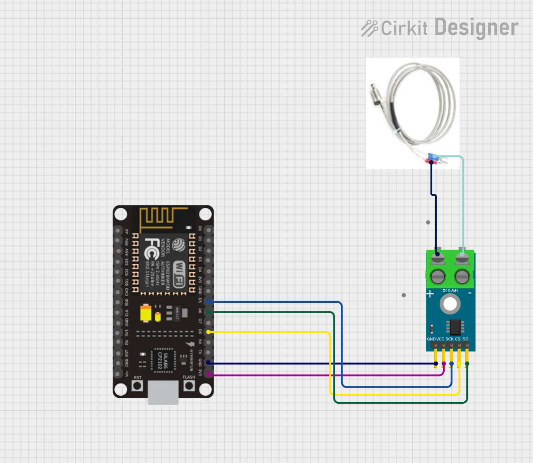
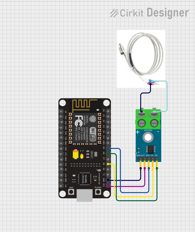
  1. Connect the VCC pin to the power supply (3.0V to 5.5V).
  2. Connect the GND pin to the ground of the power supply.
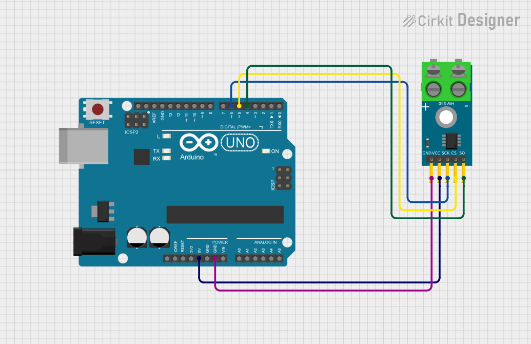
  3. Connect the SCK, CS, and SO pins to the corresponding SPI pins on your microcontroller (e.g., Arduino UNO).
  4. Attach a K-type thermocouple to the thermocouple inputs on the breakout board.

Important Considerations and Best Practices

  • Ensure that the thermocouple wires are connected correctly; the polarity matters.
  • Avoid placing the breakout board near heat sources or components that generate heat to prevent false readings.
  • Use twisted pair wires for the thermocouple to reduce electrical noise and improve measurement accuracy.
  • Keep the thermocouple wires away from electrical noise sources such as motors, inverters, and high current traces.

Example Code for Arduino UNO

#include <SPI.h>

// Define the CS pin for the MAX6675
const int csPin = 10;

void setup() {
  // Start the Serial communication
  Serial.begin(9600);
  
  // Set the CS pin as an output
  pinMode(csPin, OUTPUT);
  
  // Initialize the SPI library
  SPI.begin();
}

void loop() {
  // Read the temperature from the MAX6675
  float temperature = readTemperature();
  
  // Print the temperature to the Serial Monitor
  Serial.print("Temperature: ");
  Serial.print(temperature);
  Serial.println(" C");
  
  // Wait for 1 second before reading the temperature again
  delay(1000);
}

float readTemperature() {
  // Pull the CS pin low to enable the MAX6675
  digitalWrite(csPin, LOW);
  
  // Wait for the MAX6675 to stabilize
  delay(1);
  
  // Read two bytes from the MAX6675
  uint16_t v = SPI.transfer16(0x0000);
  
  // Pull the CS pin high to disable the MAX6675
  digitalWrite(csPin, HIGH);
  
  // Check if the thermocouple is disconnected
  if (v & 0x4) {
    // Return an error value or handle the disconnection
    return NAN;
  }
  
  // Process the raw data to extract the temperature
  v >>= 3;
  
  // Convert the value to Celsius
  return v * 0.25;
}

Troubleshooting and FAQs

Common Issues Users Might Face

  • Incorrect Temperature Readings: Ensure that the thermocouple is properly connected and that there are no shorts or open circuits.
  • No Data Output: Check the SPI connections and ensure that the CS pin is being driven correctly.
  • Thermocouple Disconnection Error: The MAX6675 will output an error if the thermocouple is disconnected. Check the connections and the integrity of the thermocouple.

Solutions and Tips for Troubleshooting

  • Double-check wiring and solder joints for any loose connections or shorts.
  • Use a multimeter to verify the power supply voltage at the VCC pin.
  • Ensure that the microcontroller's SPI settings (clock polarity, phase, and frequency) match the requirements of the MAX6675.
  • If experiencing erratic temperature readings, consider adding a capacitor between VCC and GND near the breakout board to stabilize the power supply.

FAQs

Q: Can I use a thermocouple other than K-type with this breakout? A: No, the MAX6675 is specifically designed for K-type thermocouples.

Q: What is the maximum length for the thermocouple wires? A: There is no strict maximum length, but longer wires may pick up more electrical noise, affecting accuracy. Use twisted pair wires and keep the length reasonable.

Q: How can I calibrate the temperature readings? A: The MAX6675 is factory-calibrated. However, for critical applications, you can compare readings with a known accurate thermometer and apply a software offset if necessary.

Q: Is the MAX6675 affected by ambient temperature? A: The MAX6675 compensates for changes in ambient temperature but ensure the breakout board itself is not exposed to extreme temperatures that could affect its operation.