
How to Use Arduino GSM Shield: Examples, Pinouts, and Specs
 Design with Arduino GSM Shield in Cirkit Designer
Introduction
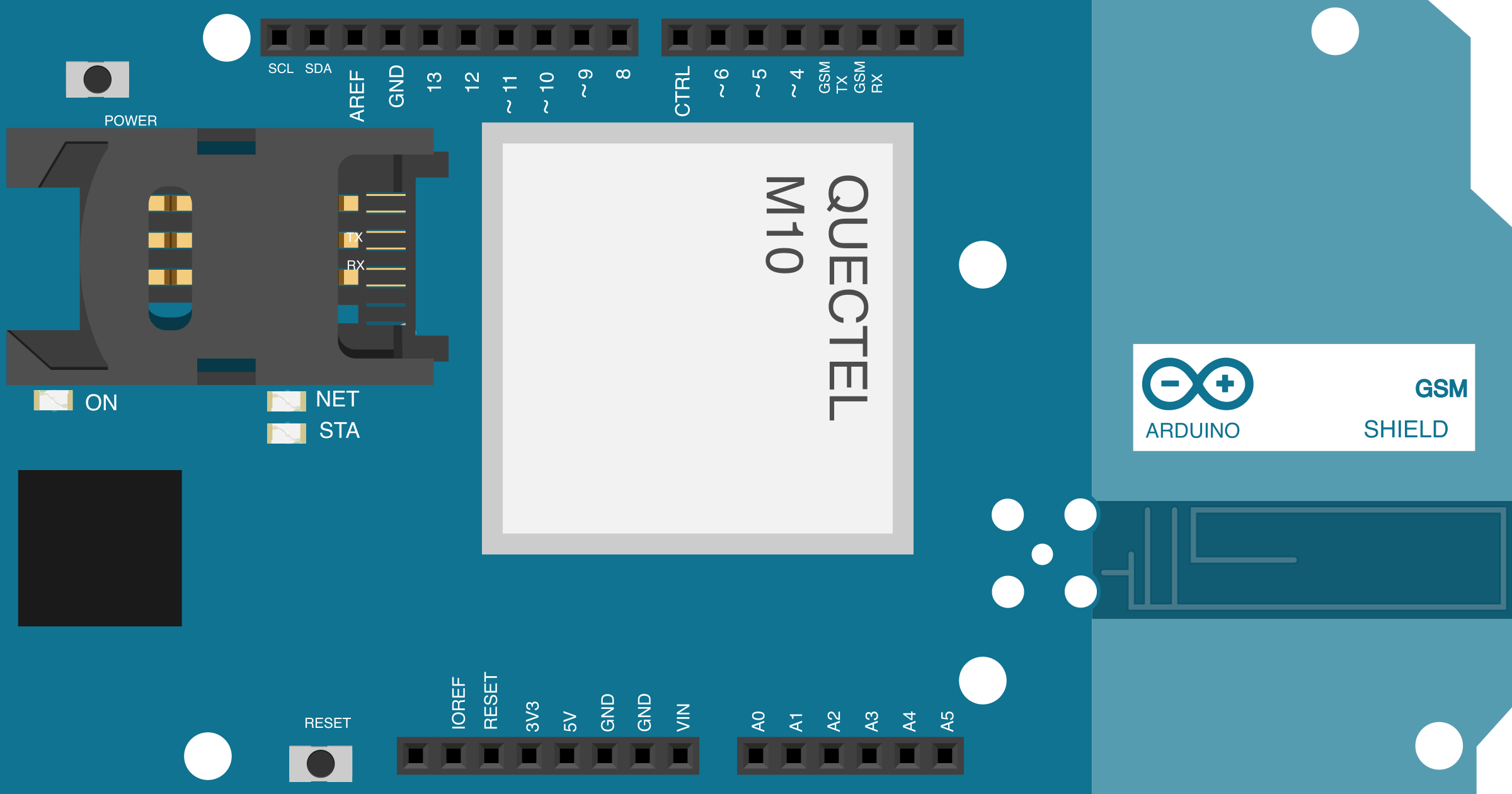
The Arduino GSM Shield is a hardware module designed to enable Arduino boards to connect to GSM (Global System for Mobile Communications) networks. This shield allows users to send and receive SMS messages, make voice calls, and access the internet via GPRS. It is an ideal solution for projects requiring remote communication, such as IoT devices, home automation, and GPS tracking systems.
Explore Projects Built with Arduino GSM Shield
 Open Project in Cirkit Designer
 Open Project in Cirkit Designer
 Open Project in Cirkit Designer
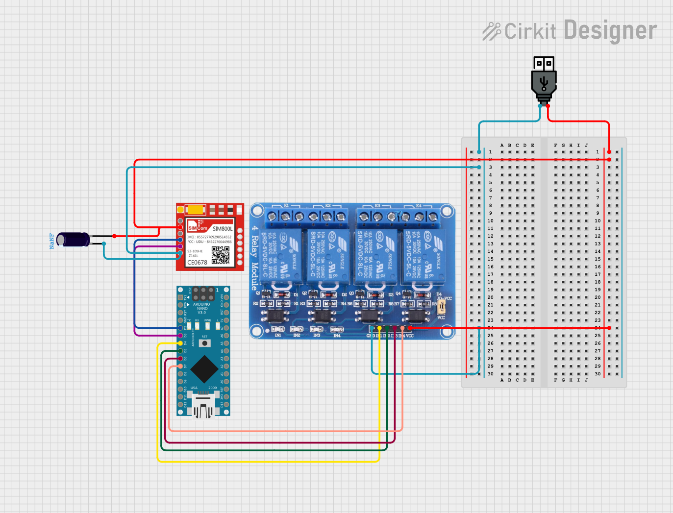 Open Project in Cirkit Designer
Explore Projects Built with Arduino GSM Shield
Open Project in Cirkit DesignerOpen Project in Cirkit DesignerOpen Project in Cirkit DesignerOpen Project in Cirkit DesignerCommon Applications and Use Cases
- Sending and receiving SMS messages for remote notifications
- Making voice calls for communication-based projects
- Internet connectivity via GPRS for IoT applications
- Remote monitoring and control systems
- GPS tracking and location-based services
Technical Specifications
The Arduino GSM Shield is based on the Quectel M10 GSM/GPRS module and is compatible with most Arduino boards. Below are the key technical details:
Key Technical Details
- Operating Voltage: 5V (supplied by the Arduino board)
- Power Consumption:
- Idle: ~10mA
- Active (GPRS): ~250mA
- Peak: ~2A (during GSM transmission bursts)
- Frequency Bands: Quad-band (850/900/1800/1900 MHz)
- Data Connectivity: GPRS Class 10
- SIM Card Slot: Standard SIM card (2G)
- Antenna Connector: SMA connector for external antenna
- Communication Interface: UART (via Arduino pins 2 and 3)
- Dimensions: 68.6mm x 53.4mm (standard Arduino shield size)
Pin Configuration and Descriptions
The Arduino GSM Shield uses the following pins for communication and control:
| Pin | Name | Description |
|---|---|---|
| 2 | RXD | UART Receive pin (connected to Arduino TX for serial communication) |
| 3 | TXD | UART Transmit pin (connected to Arduino RX for serial communication) |
| 7 | Power Key | Used to turn the GSM module on/off |
| 8 | Status | Indicates the GSM module's power status |
| 9 | Reset | Resets the GSM module |
| GND | Ground | Common ground connection |
| VIN | Power Input | Supplies power to the GSM Shield (5V from Arduino board) |
Usage Instructions
How to Use the Arduino GSM Shield in a Circuit
- Attach the Shield: Place the GSM Shield on top of your Arduino board, ensuring the pins align correctly.
- Insert a SIM Card: Insert a standard 2G SIM card into the SIM card slot on the shield.
- Connect the Antenna: Attach an external GSM antenna to the SMA connector for better signal reception.
- Power the Arduino: Connect the Arduino board to a power source (USB or external power supply).
- Upload Code: Use the Arduino IDE to upload a sketch that communicates with the GSM Shield.
Important Considerations and Best Practices
- Ensure the SIM card has an active data plan and supports 2G networks.
- Use a power supply capable of providing sufficient current (at least 2A) to handle GSM transmission bursts.
- Place the antenna in an open area for optimal signal strength.
- Avoid using the shield in areas with poor GSM network coverage.
- Use the
GSMlibrary provided by Arduino for easier integration and communication with the shield.
Example Code for Sending an SMS
Below is an example sketch for sending an SMS using the Arduino GSM Shield:
#include <GSM.h>

// PIN for the SIM card (if required by your network provider)
#define PINNUMBER ""

// Initialize GSM library
GSM gsmAccess; // Handles GSM connection
GSM_SMS sms;   // Handles SMS functionality

void setup() {
  // Start serial communication for debugging
  Serial.begin(9600);
  Serial.println("Initializing GSM module...");

  // Connect to the GSM network
  bool connected = false;
  while (!connected) {
    if (gsmAccess.begin(PINNUMBER) == GSM_READY) {
      connected = true;
      Serial.println("GSM module connected!");
    } else {
      Serial.println("Failed to connect. Retrying...");
      delay(1000);
    }
  }
}

void loop() {
  // Send an SMS
  Serial.println("Sending SMS...");
  sms.beginSMS("+1234567890"); // Replace with the recipient's phone number
  sms.print("Hello from Arduino GSM Shield!"); // Message content
  sms.endSMS();
  Serial.println("SMS sent!");

  // Wait before sending another SMS
  delay(60000); // 1-minute delay
}
Troubleshooting and FAQs
Common Issues and Solutions
GSM Shield Not Connecting to the Network
- Ensure the SIM card is inserted correctly and has an active plan.
- Check that the antenna is securely connected and placed in an area with good signal strength.
- Verify that the GSM network supports 2G connectivity.
Power Issues
- Use a power supply capable of providing at least 2A of current.
- Check all connections to ensure the shield is receiving power.
Serial Communication Problems
- Ensure the correct pins (2 and 3) are used for UART communication.
- Avoid using the Arduino's default Serial Monitor while communicating with the shield.
SMS Not Sending
- Verify the recipient's phone number is in the correct format (e.g., with country code).
- Check that the SIM card has sufficient credit or an active SMS plan.
FAQs
Q: Can the GSM Shield work with 3G or 4G networks?
A: No, the GSM Shield only supports 2G networks. Ensure your SIM card and network provider support 2G connectivity.
Q: How do I check the signal strength?
A: Use the GSM library's getSignalStrength() function to retrieve the signal strength in your code.
Q: Can I use the GSM Shield with an Arduino Mega?
A: Yes, but you may need to modify the UART pins used for communication. Refer to the Arduino GSM Shield documentation for details.
Q: Is it possible to receive calls with the GSM Shield?
A: Yes, the GSM Shield supports voice calls. Use the GSMVoiceCall class in the GSM library to handle incoming and outgoing calls.