How to Use LoRa Ra-02 SX1278: Examples, Pinouts, and Specs
Introduction
The LoRa Ra-02 SX1278 module is a wireless communication device that leverages the capabilities of the SX1278 transceiver chip to provide long-range, low-power communication using the LoRa (Long Range) protocol. This module is widely used in various applications such as remote sensors, home automation, IoT devices, and telemetry, due to its ability to transmit data over long distances while maintaining low power consumption.
Explore Projects Built with LoRa Ra-02 SX1278

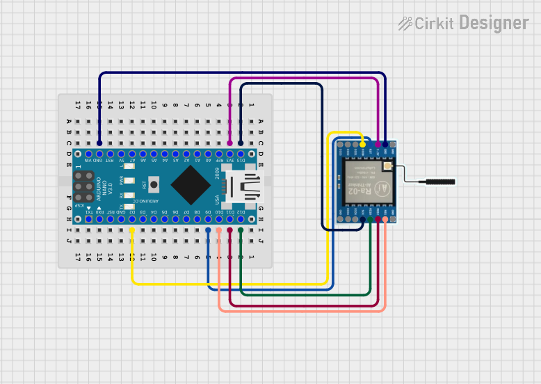
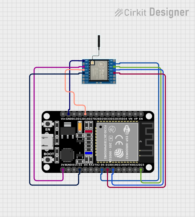
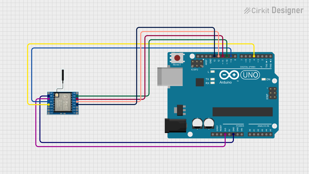
Explore Projects Built with LoRa Ra-02 SX1278
Common Applications and Use Cases
- Remote environmental monitoring
- Smart agriculture
- Home and industrial automation
- Asset tracking
- Wireless alarm and security systems
Technical Specifications
Key Technical Details
- Frequency Range: 433 MHz (LoRa Band)
- Modulation: LoRa Spread Spectrum
- Output Power: +20 dBm - 100 mW
- Sensitivity: -139 dBm at LoRa & 62.5 KHz & SF=12 & 146bps
- Data Transfer Rate: 0.018 kbps - 37.5 kbps
- Operating Voltage: 1.8 - 3.7V, typical 3.3V
- Operating Temperature Range: -40°C to +85°C
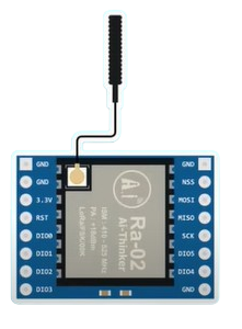
Pin Configuration and Descriptions
| Pin Number | Name | Description |
|---|---|---|
| 1 | GND | Ground connection |
| 2 | VCC | Power supply (1.8V - 3.7V) |
| 3 | DIO0 | Digital I/O, used for interrupt signaling |
| 4 | DIO1 | Digital I/O, additional interrupt signaling |
| 5 | DIO2 | Digital I/O, typically not used |
| 6 | DIO3 | Digital I/O, typically not used |
| 7 | DIO4 | Digital I/O, typically not used |
| 8 | DIO5 | Digital I/O, typically not used |
| 9 | SCK | SPI Clock |
| 10 | MISO | SPI Master In Slave Out |
| 11 | MOSI | SPI Master Out Slave In |
| 12 | NSS | SPI Chip Select (Active Low) |
| 13 | RESET | Module reset signal (Active Low) |
| 14 | ANT | Antenna connection |
Usage Instructions
How to Use the Component in a Circuit
- Power Supply: Connect the VCC pin to a 3.3V power source and the GND pin to the ground.
- SPI Interface: Connect SCK, MISO, MOSI, and NSS to the corresponding SPI pins of the microcontroller.
- Interrupts: Connect DIO0 to an interrupt-capable GPIO pin on the microcontroller for receive and transmit interrupt handling.
- Reset: Connect the RESET pin to a GPIO pin on the microcontroller to control the reset function programmatically.
- Antenna: Attach an appropriate antenna to the ANT pin for signal transmission and reception.
Important Considerations and Best Practices
- Ensure that the power supply is stable and within the specified voltage range.
- Use a level shifter if interfacing with a 5V microcontroller to avoid damaging the module.
- Place the module away from noise sources and ensure the antenna has a clear line of sight for optimal range.
- Follow local regulations regarding the use of the 433 MHz frequency band.
Example Code for Arduino UNO
#include <SPI.h>
#include <LoRa.h>

// Define the LoRa module pins
#define SS      10
#define RST     9
#define DI0     2

void setup() {
  Serial.begin(9600);
  while (!Serial);

  Serial.println("LoRa Sender");

  // Initialize LoRa module
  LoRa.setPins(SS, RST, DI0);

  if (!LoRa.begin(433E6)) {
    Serial.println("Starting LoRa failed!");
    while (1);
  }
}

void loop() {
  Serial.print("Sending packet: ");
  Serial.println(counter);

  // Send a message
  LoRa.beginPacket();
  LoRa.print("hello ");
  LoRa.print(counter);
  LoRa.endPacket();

  counter++;

  delay(5000);
}
Troubleshooting and FAQs
Common Issues Users Might Face
- No Communication: Ensure the antenna is properly connected and the module is not placed near metal objects or electronic noise sources.
- Short Range: Check for obstacles between the modules, antenna orientation, and ensure the use of an appropriate antenna.
- Power Issues: Verify that the power supply is within the specified range and the connections are secure.
Solutions and Tips for Troubleshooting
- Module Not Responding: Perform a hardware reset by toggling the RESET pin or check the wiring of the SPI interface.
- Data Transmission Errors: Reduce the data rate or increase the spreading factor for better signal reliability.
- Intermittent Operation: Check for loose connections and ensure that the module is not exposed to extreme temperatures.
FAQs
Q: Can I use the LoRa Ra-02 SX1278 module with a 5V microcontroller? A: Yes, but a level shifter is required to convert the 5V signals to 3.3V to avoid damaging the module.
Q: What is the maximum range I can achieve with this module? A: The range depends on several factors, including the environment, antenna type, and data rate. Under ideal conditions, the range can be several kilometers.
Q: Is it possible to change the frequency of the module? A: The module is designed to operate at 433 MHz. Using it at other frequencies may violate local regulations and is not recommended without proper knowledge and equipment.
Q: How can I increase the data rate? A: The data rate can be increased by adjusting the bandwidth, spreading factor, and coding rate through the module's configuration settings. However, this may affect the communication range and reliability.