How to Use 3s 20A BMS: Examples, Pinouts, and Specs
Introduction
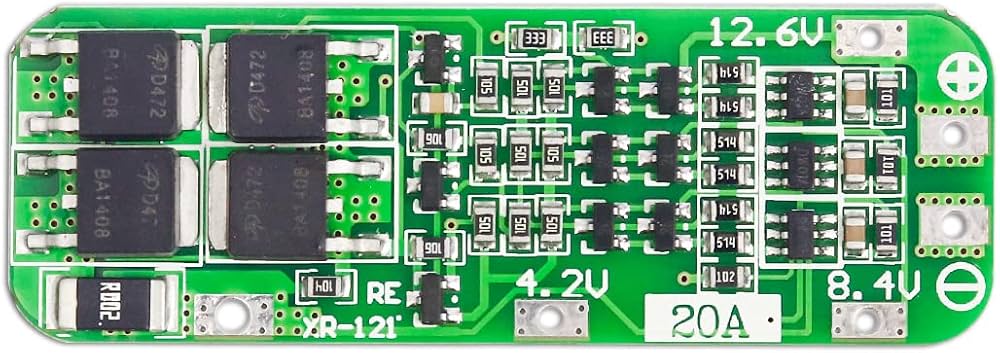
The 3s 20A BMS (Battery Management System) is an essential circuit component designed for managing a 3-cell series lithium-ion battery pack. It ensures the longevity and safety of the battery pack by providing cell balancing, overcharge protection, over-discharge protection, and short-circuit protection. This BMS is capable of handling a maximum continuous discharge current of 20A, making it suitable for various applications such as DIY power banks, portable electronics, and small electric vehicles.
Explore Projects Built with 3s 20A BMS


Explore Projects Built with 3s 20A BMS
Common Applications
- DIY power banks
- Portable electronic devices
- Electric scooters and bicycles
- Small-scale energy storage systems
Technical Specifications
Key Technical Details
| Parameter | Specification |
|---|---|
| Cell Count | 3 Series (3s) |
| Continuous Discharge Current | 20A |
| Charge Voltage | 12.6V (4.2V per cell) |
| Overcharge Protection | >4.25V per cell |
| Over-discharge Protection | <2.5V per cell |
| Short-Circuit Protection | Active |
| Balance Current | ~60mA |
Pin Configuration and Descriptions
| Pin Number | Description | Notes |
|---|---|---|
| B+ | Battery Positive | Connect to battery positive |
| B- | Battery Negative | Connect to battery negative |
| P+ | Load/Charger Positive | Connect to load/charger positive |
| P- | Load/Charger Negative | Connect to load/charger negative |
| B1 | Cell 1 Balance Lead | Connect to the positive terminal of the first cell |
| B2 | Cell 2 Balance Lead | Connect to the positive terminal of the second cell |
| B3 | Cell 3 Balance Lead | Connect to the positive terminal of the third cell |
Usage Instructions
How to Use the Component in a Circuit
- Battery Connection: Connect the battery pack to the BMS, ensuring that the positive and negative terminals are connected to B+ and B- respectively. Additionally, connect the balance leads to B1, B2, and B3 according to the cell order in the battery pack.
- Load Connection: Connect the load or charger to the P+ and P- terminals. Ensure that the load does not exceed the BMS's maximum continuous discharge current of 20A.
- Charging: When charging the battery pack, the BMS will monitor individual cell voltages and activate balancing to maintain uniform charge levels across all cells.
Important Considerations and Best Practices
- Always ensure proper polarity when connecting the battery and load to the BMS.
- Do not exceed the maximum continuous discharge current of 20A to prevent damage.
- Use appropriate gauge wires for the current to minimize resistance and heat.
- Ensure the BMS is placed in a location with adequate ventilation to prevent overheating.
Troubleshooting and FAQs
Common Issues
- Battery Not Charging: Check if the BMS has entered protection mode due to over-discharge. Charge the battery slightly with a low current to reset the BMS.
- Uneven Cell Voltages: Ensure that all balance leads are properly connected and that the BMS is functioning correctly. If the issue persists, individual cells may be faulty.
Solutions and Tips for Troubleshooting
- BMS Not Balancing: Verify that all connections are secure and that the BMS is not damaged. Check individual cell voltages to diagnose potential cell issues.
- BMS Overheating: Reduce the load on the battery or improve ventilation around the BMS to prevent overheating.
FAQs
Q: Can I use the 3s 20A BMS with a battery pack that has a higher capacity? A: Yes, as long as the battery pack is a 3-cell series configuration and the discharge current does not exceed 20A.
Q: What should I do if one of the cells in my battery pack is consistently underperforming? A: Replace the underperforming cell if possible. If the issue persists, the BMS may need to be replaced.
Q: How do I know if the BMS is balancing the cells correctly? A: Measure the voltage of each cell during the charging process. The voltages should gradually converge as the BMS balances the cells.
Q: Is it possible to bypass the BMS for a higher discharge current? A: Bypassing the BMS is not recommended as it removes critical protection features and can lead to battery damage or safety hazards.
Example Code for Arduino UNO
// This example code is designed to read the voltage of each cell
// through the balance leads and display it on the serial monitor.
// Note: Additional circuitry is required to interface the BMS with Arduino.

#include <Wire.h>

// Define analog pins connected to the balance leads
const int cell1Pin = A0;
const int cell2Pin = A1;
const int cell3Pin = A2;

void setup() {
  Serial.begin(9600);
}

void loop() {
  // Read the analog values from each cell
  int cell1Value = analogRead(cell1Pin);
  int cell2Value = analogRead(cell2Pin);
  int cell3Value = analogRead(cell3Pin);

  // Convert the analog values to voltages
  float cell1Voltage = cell1Value * (5.0 / 1023.0);
  float cell2Voltage = cell2Value * (5.0 / 1023.0);
  float cell3Voltage = cell3Value * (5.0 / 1023.0);

  // Print the voltages to the serial monitor
  Serial.print("Cell 1 Voltage: ");
  Serial.print(cell1Voltage);
  Serial.println(" V");
  Serial.print("Cell 2 Voltage: ");
  Serial.print(cell2Voltage);
  Serial.println(" V");
  Serial.print("Cell 3 Voltage: ");
  Serial.print(cell3Voltage);
  Serial.println(" V");

  // Wait for a second before reading again
  delay(1000);
}
Please note that the above code is a simple demonstration and does not include the necessary circuitry to safely connect the Arduino to the BMS. Always ensure that the interfacing circuitry is designed to handle the voltage levels of the battery pack and that it provides proper isolation and voltage level shifting as required.