How to Use RC 12V relay module single channel: Examples, Pinouts, and Specs
Introduction
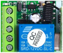
The RC 12V Relay Module Single Channel is an electronic component designed to control high-voltage devices using a low-voltage signal. It operates at 12V and is ideal for applications requiring the switching of electrical circuits. This module is commonly used in home automation, industrial control systems, and DIY electronics projects. Its single-channel design makes it suitable for controlling one device at a time, such as lights, fans, or other appliances.
Explore Projects Built with RC 12V relay module single channel


Explore Projects Built with RC 12V relay module single channel
Common Applications and Use Cases
- Home automation systems (e.g., controlling lights or appliances remotely)
- Industrial equipment control
- DIY electronics projects
- Robotics and IoT applications
- Motor and pump control
Technical Specifications
The RC 12V Relay Module Single Channel is built to handle a wide range of applications. Below are its key technical details:
General Specifications
| Parameter | Value |
|---|---|
| Operating Voltage | 12V DC |
| Trigger Voltage | 3-12V DC |
| Maximum Load Voltage | 250V AC / 30V DC |
| Maximum Load Current | 10A |
| Relay Type | SPDT (Single Pole Double Throw) |
| Channel Count | 1 |
| Isolation | Optocoupler-based isolation |
| Dimensions | ~50mm x 26mm x 18mm |
Pin Configuration and Descriptions
| Pin Name | Description |
|---|---|
| VCC | Connect to the 12V DC power supply to power the relay module. |
| GND | Connect to the ground of the power supply. |
| IN | Signal input pin. A low-voltage signal (3-12V DC) activates the relay. |
| COM | Common terminal for the relay switch. |
| NO | Normally Open terminal. Connect the load here for default OFF state. |
| NC | Normally Closed terminal. Connect the load here for default ON state. |
Usage Instructions
How to Use the RC 12V Relay Module in a Circuit
- Power the Module: Connect the VCC pin to a 12V DC power supply and the GND pin to the ground.
- Signal Input: Connect the IN pin to a microcontroller (e.g., Arduino UNO) or any other control circuit capable of providing a 3-12V DC signal.
- Load Connection:
- For devices that should remain OFF by default, connect the load between the COM and NO terminals.
- For devices that should remain ON by default, connect the load between the COM and NC terminals.
- Control the Relay: Send a HIGH or LOW signal to the IN pin to toggle the relay state.
Important Considerations and Best Practices
- Isolation: The module uses an optocoupler for isolation, ensuring safe operation when controlling high-voltage devices.
- Power Supply: Ensure the 12V power supply is stable and capable of providing sufficient current for the relay.
- Load Ratings: Do not exceed the maximum load voltage (250V AC / 30V DC) or current (10A) to avoid damage.
- Signal Voltage: Ensure the control signal voltage is within the 3-12V DC range to activate the relay reliably.
- Safety: When working with high-voltage devices, take necessary precautions to avoid electric shock or damage.
Example: Connecting to an Arduino UNO
Below is an example of how to connect and control the RC 12V Relay Module using an Arduino UNO:
Circuit Connections
- Connect the VCC pin of the relay module to the Arduino's 5V pin.
- Connect the GND pin of the relay module to the Arduino's GND pin.
- Connect the IN pin of the relay module to digital pin 7 on the Arduino.
- Connect the load (e.g., a light bulb) to the COM and NO terminals of the relay.
Arduino Code
// Define the pin connected to the relay module
const int relayPin = 7;

void setup() {
  // Set the relay pin as an output
  pinMode(relayPin, OUTPUT);

  // Ensure the relay is OFF at startup
  digitalWrite(relayPin, LOW);
}

void loop() {
  // Turn the relay ON
  digitalWrite(relayPin, HIGH);
  delay(5000); // Keep the relay ON for 5 seconds

  // Turn the relay OFF
  digitalWrite(relayPin, LOW);
  delay(5000); // Keep the relay OFF for 5 seconds
}
Troubleshooting and FAQs
Common Issues and Solutions
Relay Not Activating:
- Ensure the VCC and GND pins are properly connected to a 12V DC power supply.
- Verify that the control signal voltage is within the 3-12V DC range.
- Check for loose or incorrect wiring.
Load Not Switching:
- Confirm that the load is connected to the correct terminals (COM and NO/NC).
- Ensure the load does not exceed the relay's maximum voltage or current ratings.
Arduino Not Controlling the Relay:
- Verify that the IN pin is connected to the correct Arduino digital pin.
- Check the Arduino code for errors and ensure the relay pin is set as an output.
Relay Clicking but No Output:
- Check the wiring of the load and ensure it is properly connected to the relay terminals.
- Test the relay with a multimeter to confirm proper operation.
FAQs
Q: Can I use this relay module with a 5V power supply?
A: No, the RC 12V Relay Module requires a 12V DC power supply for proper operation. Using a lower voltage may result in unreliable performance.
Q: Is the module safe for high-voltage applications?
A: Yes, the module is designed for high-voltage applications, but always follow safety guidelines and ensure proper insulation.
Q: Can I control the relay with a Raspberry Pi?
A: Yes, the relay can be controlled with a Raspberry Pi, but you may need a level shifter or transistor circuit to ensure the control signal is within the required range.
Q: What is the purpose of the NC terminal?
A: The NC (Normally Closed) terminal allows the load to remain ON by default when the relay is not activated.