How to Use 4in1 ESC(NOTE: NOT ACTUALLY 120A): Examples, Pinouts, and Specs
Introduction
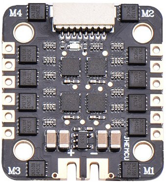
The JHEMCU EM-120A 4 IN1 ESC is a compact and efficient electronic speed controller designed specifically for multi-rotor drones. By integrating four ESCs into a single unit, it simplifies wiring, reduces weight, and saves valuable space in drone builds. This ESC is ideal for hobbyists and professionals building quadcopters or other multi-rotor platforms.
Important Note: While the product is labeled as "120A," the actual current rating may be lower. Users are advised to verify the specifications and ensure compatibility with their drone's motors and power requirements.
Explore Projects Built with 4in1 ESC(NOTE: NOT ACTUALLY 120A)


Explore Projects Built with 4in1 ESC(NOTE: NOT ACTUALLY 120A)
Common Applications
- Multi-rotor drones (quadcopters, hexacopters, etc.)
- FPV (First-Person View) racing drones
- Aerial photography and videography platforms
- Lightweight and compact drone builds
Technical Specifications
Key Technical Details
| Parameter | Specification |
|---|---|
| Manufacturer | JHEMCU |
| Part ID | EM-120A 4 IN1 ESC |
| Input Voltage Range | 2S–6S LiPo (7.4V–25.2V) |
| Continuous Current (per ESC) | ~30A (verify actual rating) |
| Burst Current (per ESC) | ~40A (for a few seconds) |
| Firmware | BLHeli_S |
| Signal Input | DShot, PWM, OneShot, MultiShot |
| Dimensions | 36mm x 36mm (30.5mm mounting holes) |
| Weight | ~12g |
| Connector Type | XT60 (power input), solder pads (motors) |
Pin Configuration and Descriptions
The EM-120A 4 IN1 ESC features solder pads for motor connections and a connector for signal input. Below is the pin configuration:
Signal Input Connector
| Pin Number | Label | Description |
|---|---|---|
| 1 | GND | Ground |
| 2 | VBAT | Battery voltage (for telemetry) |
| 3 | M1 | Signal input for Motor 1 |
| 4 | M2 | Signal input for Motor 2 |
| 5 | M3 | Signal input for Motor 3 |
| 6 | M4 | Signal input for Motor 4 |
Motor Output Pads
| Pad Label | Description |
|---|---|
| M1+ / M1- | Positive and negative terminals for Motor 1 |
| M2+ / M2- | Positive and negative terminals for Motor 2 |
| M3+ / M3- | Positive and negative terminals for Motor 3 |
| M4+ / M4- | Positive and negative terminals for Motor 4 |
Usage Instructions
How to Use the EM-120A 4 IN1 ESC in a Circuit
Power Connection:
- Connect the ESC to a 2S–6S LiPo battery using the XT60 connector.
- Ensure the battery voltage matches the ESC's input voltage range (7.4V–25.2V).
Motor Connections:
- Solder the motor wires to the corresponding output pads (M1, M2, M3, M4).
- Ensure correct polarity (M+ for positive, M- for negative).
Signal Input:
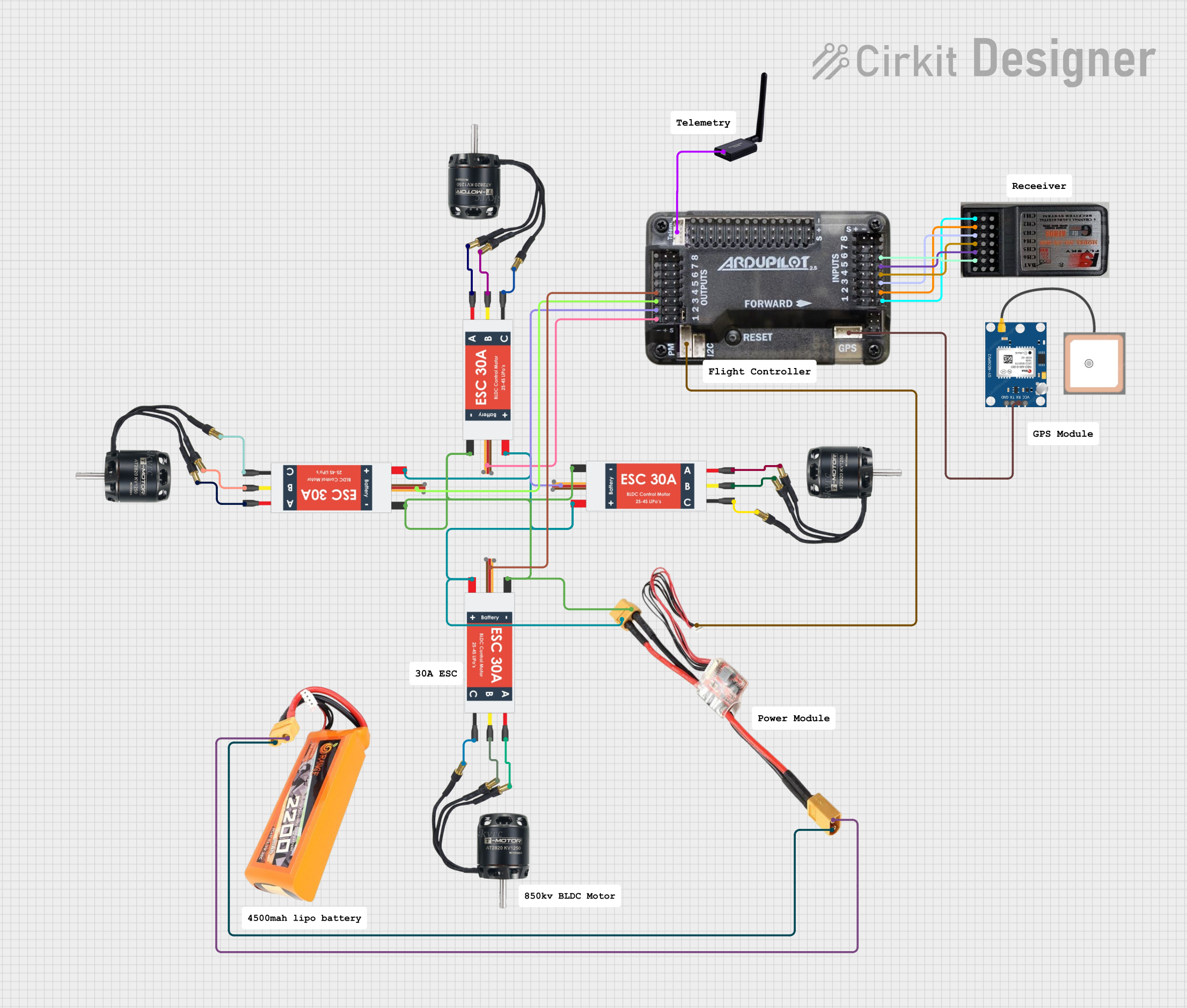
- Connect the signal input pins (M1, M2, M3, M4) to the flight controller's motor output pins.
- Use the GND pin to connect the ESC's ground to the flight controller's ground.
Firmware Configuration:
- Use BLHeli_S software to configure the ESC settings (e.g., motor direction, signal type).
- Ensure the ESC is set to the correct protocol (e.g., DShot, PWM) as per your flight controller.
Testing:
- Power on the system and test each motor individually to ensure proper operation.
- Verify motor direction and adjust in BLHeli_S if necessary.
Important Considerations and Best Practices
- Verify Current Ratings: Do not assume the ESC can handle 120A. Check the actual current requirements of your motors and ensure they are within the ESC's safe operating range (~30A continuous).
- Cooling: Ensure adequate airflow over the ESC to prevent overheating during operation.
- Soldering: Use high-quality solder and ensure strong connections to avoid electrical issues.
- Firmware Updates: Keep the BLHeli_S firmware updated for optimal performance and compatibility.
- Signal Protocol: Use DShot if supported by your flight controller for better performance and reliability.
Example: Connecting to an Arduino UNO
While the EM-120A is typically used with flight controllers, it can also be controlled using an Arduino UNO for testing purposes. Below is an example code snippet to control one motor using PWM:
// Example code to control one motor using Arduino UNO and EM-120A ESC
// Connect the ESC signal wire (e.g., M1) to Arduino pin 9

#include <Servo.h> // Include Servo library for PWM control

Servo motor1; // Create a Servo object for the motor

void setup() {
  motor1.attach(9); // Attach ESC signal wire to pin 9
  motor1.writeMicroseconds(1000); // Send minimum throttle signal
  delay(2000); // Wait for ESC to initialize
}

void loop() {
  motor1.writeMicroseconds(1500); // Set throttle to mid-range
  delay(5000); // Run motor for 5 seconds

  motor1.writeMicroseconds(1000); // Stop motor
  delay(5000); // Wait for 5 seconds
}
Note: Ensure the ESC is powered by a suitable LiPo battery when testing with Arduino.
Troubleshooting and FAQs
Common Issues and Solutions
Motors Not Spinning:
- Check signal connections between the ESC and flight controller.
- Verify the ESC is receiving power from the battery.
- Ensure the ESC firmware is configured correctly (e.g., motor direction, protocol).
Overheating:
- Ensure proper airflow over the ESC.
- Verify the motors are not drawing more current than the ESC's rated capacity.
Motor Stuttering or Jerking:
- Check solder connections on the motor output pads.
- Verify the signal protocol (e.g., DShot) matches the flight controller's configuration.
ESC Not Recognized by BLHeli_S:
- Ensure the ESC is properly connected to the flight controller.
- Use a compatible USB adapter or interface for BLHeli_S configuration.
FAQs
Q: Can I use this ESC with a 7-inch quadcopter?
A: Yes, as long as the motors' current draw does not exceed the ESC's rated capacity (~30A continuous).
Q: Is this ESC compatible with DShot1200?
A: No, the EM-120A supports DShot600 and lower protocols.
Q: Can I use this ESC with a 4S LiPo battery?
A: Yes, the ESC supports 2S–6S LiPo batteries, including 4S.
Q: How do I reverse motor direction?
A: Use the BLHeli_S software to reverse the motor direction for any of the four ESCs.
By following this documentation, users can effectively integrate and operate the JHEMCU EM-120A 4 IN1 ESC in their drone builds.