Cirkit Designer Logo
Cirkit Designer
Your all-in-one circuit design IDE
Home / 
Component Documentation

How to Use DRV8825: Examples, Pinouts, and Specs

Image of DRV8825
Cirkit Designer LogoDesign with DRV8825 in Cirkit Designer

Introduction

The DRV8825 is a versatile microstepping driver for controlling bipolar stepper motors. With its adjustable current limiting, built-in over-current and over-temperature protection, and six microstep resolutions, it is suitable for a wide range of applications, including 3D printers, CNC machines, and robotics.

Explore Projects Built with DRV8825

Use Cirkit Designer to design, explore, and prototype these projects online. Some projects support real-time simulation. Click "Open Project" to start designing instantly!
ATmega328P Microcontroller-Driven Stepper Motor with DRV8825
Image of Shutter for laser: A project utilizing DRV8825 in a practical application
This circuit is designed to control a bipolar stepper motor using a DRV8825 stepper motor driver, which is interfaced with a Nano 3.0 ATmega328P microcontroller. The microcontroller sends step and direction signals to the DRV8825, which in turn drives the stepper motor's coils. Power is supplied to the system through a 5V adapter for the logic and a DC power source for the motor, with an electrolytic capacitor for voltage smoothing on the motor supply.
Cirkit Designer LogoOpen Project in Cirkit Designer
ESP32-Controlled Miniature Golf Course with Interactive Features
Image of aiden: A project utilizing DRV8825 in a practical application
This circuit is designed for an interactive miniature golf course feature, which includes a stepper motor controlled by a DRV8825 driver for a rotating windmill obstacle, two IR sensors for detecting the presence of a golf ball, and two LED strips for visual effects. An ESP32 microcontroller is programmed to manage the sensors, control the stepper motor, drive the LED strips, and interface with a DFPlayer Mini MP3 module for sound effects. The circuit is powered by a 12V power supply with a buck converter to step down the voltage for the logic components, and electrolytic capacitors are used for voltage smoothing.
Cirkit Designer LogoOpen Project in Cirkit Designer
ESP32-Powered Wi-Fi Controlled Robotic Car with OLED Display and Ultrasonic Sensor
Image of playbot: A project utilizing DRV8825 in a practical application
This circuit is a battery-powered system featuring an ESP32 microcontroller that controls an OLED display, a motor driver for two hobby motors, an ultrasonic sensor for distance measurement, and a DFPlayer Mini for audio output through a loudspeaker. The TP4056 module manages battery charging, and a step-up boost converter provides a stable 5V supply to the components.
Cirkit Designer LogoOpen Project in Cirkit Designer
ESP32-Controlled Weather Station with BME280 Sensor and Rain Detection
Image of WEATHER: A project utilizing DRV8825 in a practical application
This circuit features an ESP32 microcontroller interfaced with a DRV8825 stepper motor driver to control a bipolar stepper motor, an Adafruit BME280 sensor for environmental monitoring, and a YL-83 rain sensor for detecting precipitation. The ESP32 uses I2C communication to interact with the BME280 sensor and digital/analog signals to read from the rain sensor's control board. Power management is handled by a solar charger power bank connected to the DRV8825 and a capacitor for voltage smoothing.
Cirkit Designer LogoOpen Project in Cirkit Designer

Explore Projects Built with DRV8825

Use Cirkit Designer to design, explore, and prototype these projects online. Some projects support real-time simulation. Click "Open Project" to start designing instantly!
Image of Shutter for laser: A project utilizing DRV8825 in a practical application
ATmega328P Microcontroller-Driven Stepper Motor with DRV8825
This circuit is designed to control a bipolar stepper motor using a DRV8825 stepper motor driver, which is interfaced with a Nano 3.0 ATmega328P microcontroller. The microcontroller sends step and direction signals to the DRV8825, which in turn drives the stepper motor's coils. Power is supplied to the system through a 5V adapter for the logic and a DC power source for the motor, with an electrolytic capacitor for voltage smoothing on the motor supply.
Cirkit Designer LogoOpen Project in Cirkit Designer
Image of aiden: A project utilizing DRV8825 in a practical application
ESP32-Controlled Miniature Golf Course with Interactive Features
This circuit is designed for an interactive miniature golf course feature, which includes a stepper motor controlled by a DRV8825 driver for a rotating windmill obstacle, two IR sensors for detecting the presence of a golf ball, and two LED strips for visual effects. An ESP32 microcontroller is programmed to manage the sensors, control the stepper motor, drive the LED strips, and interface with a DFPlayer Mini MP3 module for sound effects. The circuit is powered by a 12V power supply with a buck converter to step down the voltage for the logic components, and electrolytic capacitors are used for voltage smoothing.
Cirkit Designer LogoOpen Project in Cirkit Designer
Image of playbot: A project utilizing DRV8825 in a practical application
ESP32-Powered Wi-Fi Controlled Robotic Car with OLED Display and Ultrasonic Sensor
This circuit is a battery-powered system featuring an ESP32 microcontroller that controls an OLED display, a motor driver for two hobby motors, an ultrasonic sensor for distance measurement, and a DFPlayer Mini for audio output through a loudspeaker. The TP4056 module manages battery charging, and a step-up boost converter provides a stable 5V supply to the components.
Cirkit Designer LogoOpen Project in Cirkit Designer
Image of WEATHER: A project utilizing DRV8825 in a practical application
ESP32-Controlled Weather Station with BME280 Sensor and Rain Detection
This circuit features an ESP32 microcontroller interfaced with a DRV8825 stepper motor driver to control a bipolar stepper motor, an Adafruit BME280 sensor for environmental monitoring, and a YL-83 rain sensor for detecting precipitation. The ESP32 uses I2C communication to interact with the BME280 sensor and digital/analog signals to read from the rain sensor's control board. Power management is handled by a solar charger power bank connected to the DRV8825 and a capacitor for voltage smoothing.
Cirkit Designer LogoOpen Project in Cirkit Designer

Common Applications and Use Cases

  • Precision control in 3D printers
  • CNC machines for milling and laser cutting
  • Robotic arms and actuators
  • Automated equipment and animatronics

Technical Specifications

Key Technical Details

  • Motor Supply Voltage (VM): 8.2 – 45 V
  • Logic Supply Voltage (VDD): 2.5 – 5.25 V
  • Output Current (per channel): 1.5 A (with sufficient additional cooling up to 2.2 A)
  • Microstep Resolutions: Full, 1/2, 1/4, 1/8, 1/16, 1/32
  • Thermal Overload Protection: Yes
  • Under-voltage Lockout: Yes
  • Overcurrent Protection: Yes
  • Fault Indicator: Yes

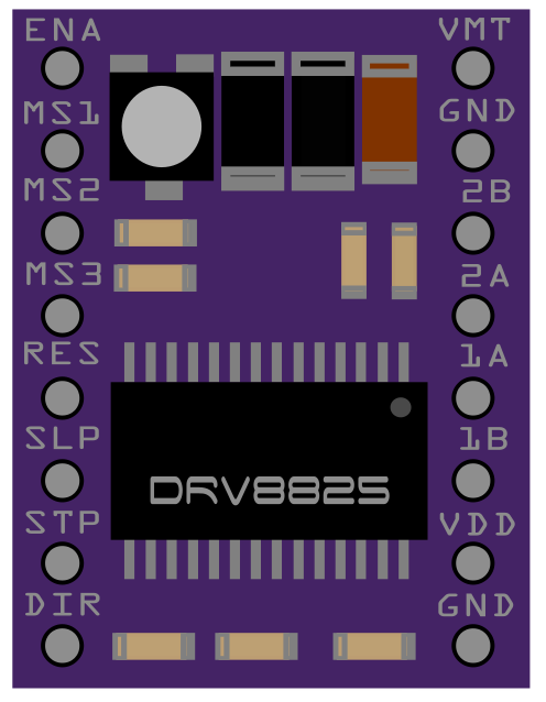
Pin Configuration and Descriptions

Pin Name Description
VM Motor voltage supply (8.2 – 45 V)
GND Ground connection
2B, 2A Motor coil 1 connections
1A, 1B Motor coil 2 connections
VDD Logic voltage supply (2.5 – 5.25 V)
RESET Resets the driver when pulled low
SLEEP Puts the driver into a low-power sleep mode when pulled low
STEP Logic input that advances the motor one step per pulse
DIR Logic input that controls the direction of the motor
M0, M1, M2 Microstep resolution selection inputs
FAULT Logic output that indicates an overcurrent or thermal shutdown condition

Usage Instructions

How to Use the Component in a Circuit

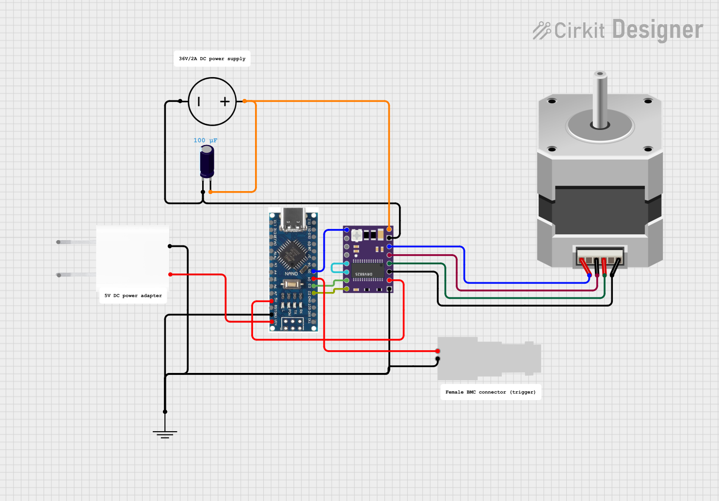
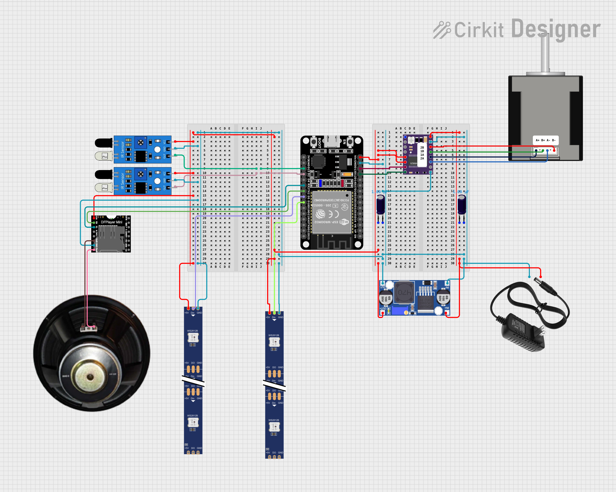
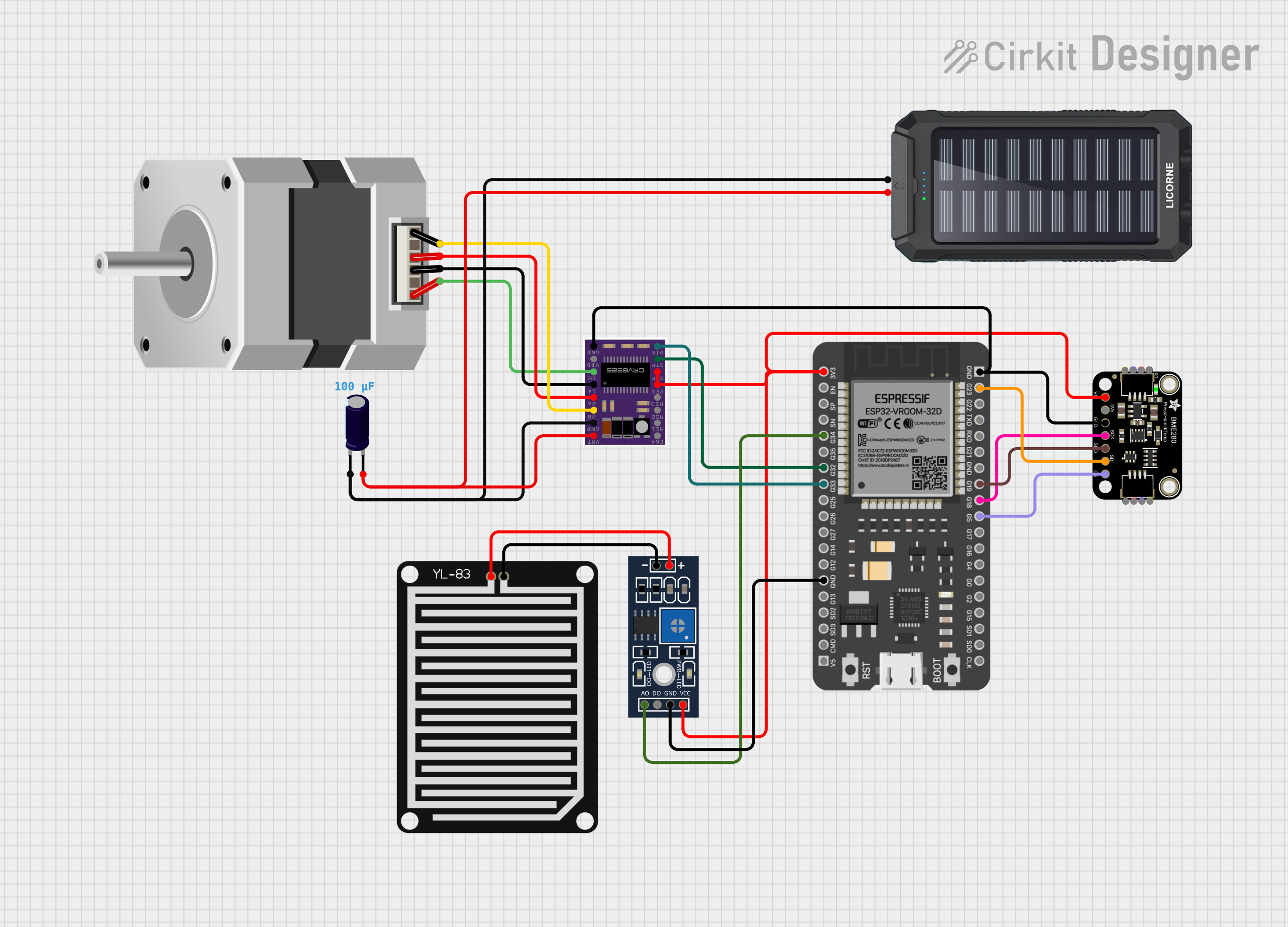
  1. Power Connections: Connect the motor supply voltage (VM) to the motor power supply and the ground (GND) to the power supply ground. Connect VDD to the logic power supply (2.5 – 5.25 V).

  2. Motor Connections: Connect the motor coils to the 2B, 2A, 1A, and 1B pins. Ensure the motor phases match the driver's outputs.

  3. Control Inputs: Connect the STEP and DIR pins to the control signals, typically from a microcontroller like an Arduino UNO. The RESET and SLEEP pins can be connected to digital outputs or tied together if not used.

  4. Microstep Selection: Set the microstep resolution by configuring the M0, M1, and M2 pins according to the truth table in the datasheet.

  5. Current Limiting: Adjust the current limiting potentiometer on the DRV8825 board to match the current rating of your stepper motor.

Important Considerations and Best Practices

  • Always ensure the power supply voltage and current ratings are within the specifications of the DRV8825.
  • Configure the current limit to prevent damage to the motor due to overcurrent.
  • Use appropriate decoupling capacitors to minimize voltage spikes on the power supply lines.
  • Avoid disconnecting the motor while the driver is powered to prevent damage to the DRV8825.
  • Provide adequate cooling if the driver is expected to handle currents near the upper limit of its capability.

Example Code for Arduino UNO

// Define the stepper motor connections and steps per revolution
#define DIR_PIN 2
#define STEP_PIN 3
#define STEPS_PER_REV 200

void setup() {
  // Set the motor control pins as outputs
  pinMode(DIR_PIN, OUTPUT);
  pinMode(STEP_PIN, OUTPUT);
}

void loop() {
  // Set the motor direction to clockwise
  digitalWrite(DIR_PIN, HIGH);

  // Move the motor one revolution
  for (int i = 0; i < STEPS_PER_REV; i++) {
    // Pulse the STEP pin to move the motor one step
    digitalWrite(STEP_PIN, HIGH);
    delayMicroseconds(1000); // Adjust the speed as necessary
    digitalWrite(STEP_PIN, LOW);
    delayMicroseconds(1000);
  }

  // Pause before changing direction
  delay(1000);

  // Set the motor direction to counterclockwise
  digitalWrite(DIR_PIN, LOW);

  // Move the motor one revolution in the other direction
  for (int i = 0; i < STEPS_PER_REV; i++) {
    digitalWrite(STEP_PIN, HIGH);
    delayMicroseconds(1000);
    digitalWrite(STEP_PIN, LOW);
    delayMicroseconds(1000);
  }

  // Pause before the next revolution
  delay(1000);
}

Troubleshooting and FAQs

Common Issues Users Might Face

  • Motor not moving: Check power supply connections, ensure the current limit is correctly set, and verify that the motor coils are properly connected.
  • Overheating: Ensure adequate cooling, and check if the current limit is set too high.
  • Inconsistent movement: Verify microstep resolution settings and ensure the control signals are clean and without noise.

Solutions and Tips for Troubleshooting

  • Motor Stalls or Misses Steps: Reduce the speed or acceleration of the motor, increase the current limit slightly, or check for mechanical obstructions.
  • Driver Resets or Shuts Down: Check for overcurrent conditions or thermal overload. Add a heatsink or improve airflow around the DRV8825.
  • Noise or Vibration: Experiment with different microstep resolutions or dampening materials to reduce resonance.

FAQs

Q: Can I run the DRV8825 without a heatsink? A: Yes, for low to moderate current levels. However, for currents approaching the upper limit, a heatsink is recommended.

Q: What is the maximum current the DRV8825 can handle? A: The DRV8825 can handle up to 1.5 A per channel without additional cooling. With sufficient cooling, it can handle up to 2.2 A per channel.

Q: How do I adjust the current limit on the DRV8825? A: Turn the potentiometer on the DRV8825 module while measuring the voltage on the REF pin or by following the VREF formula provided in the datasheet.

Q: What should I do if the FAULT pin goes high? A: Check for overcurrent or overheating conditions. Let the driver cool down and ensure that the current limit is set correctly before resuming operation.