How to Use Buzzer Module: Examples, Pinouts, and Specs
Introduction
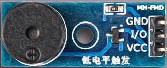
The Buzzer Module (Manufacturer: Naresh, Part ID: 1) is an electronic component designed to produce sound when an electrical signal is applied. It is widely used in applications such as alarms, notifications, timers, and sound-generating circuits. The module is compact, easy to use, and compatible with microcontrollers like Arduino, making it a popular choice for hobbyists and professionals alike.
Explore Projects Built with Buzzer Module


Explore Projects Built with Buzzer Module
Common Applications
- Alarm systems (e.g., fire alarms, burglar alarms)
- Notification systems (e.g., doorbells, timers)
- Sound effects in embedded systems
- Feedback mechanisms in user interfaces
Technical Specifications
Key Technical Details
| Parameter | Specification |
|---|---|
| Operating Voltage | 3.3V to 5V |
| Operating Current | ≤ 20mA |
| Sound Frequency | ~2 kHz |
| Sound Pressure Level | ≥ 85 dB at 10 cm |
| Dimensions | ~22mm x 12mm x 10mm |
| Weight | ~5g |
| Operating Temperature | -20°C to 70°C |
Pin Configuration and Descriptions
| Pin Name | Pin Number | Description |
|---|---|---|
| VCC | 1 | Power supply input (3.3V to 5V) |
| GND | 2 | Ground connection |
| I/O | 3 | Signal input to control the buzzer |
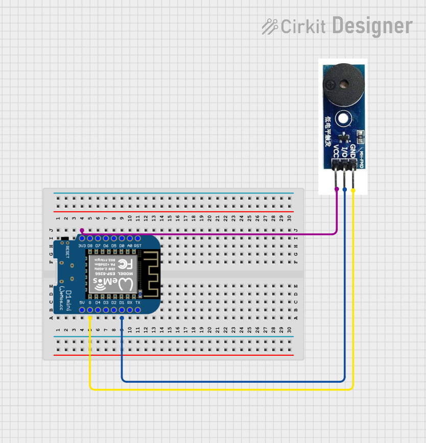
Usage Instructions
How to Use the Buzzer Module in a Circuit
- Power Supply: Connect the
VCCpin to a 3.3V or 5V power source and theGNDpin to the ground of your circuit. - Signal Input: Use the
I/Opin to send a HIGH signal (logic 1) to activate the buzzer. When the signal is LOW (logic 0), the buzzer will remain silent. - Microcontroller Integration: The module can be directly connected to a microcontroller's GPIO pin. Ensure the GPIO pin can source enough current (≤ 20mA) to drive the buzzer.
Important Considerations and Best Practices
- Power Supply: Ensure the power supply voltage is within the specified range (3.3V to 5V). Exceeding this range may damage the module.
- Signal Duration: Avoid sending continuous HIGH signals for extended periods to prevent overheating.
- Placement: Mount the buzzer module in an open area to maximize sound output. Avoid obstructing the sound hole.
- Decoupling Capacitor: For stable operation, consider adding a 0.1µF decoupling capacitor between the
VCCandGNDpins.
Example: Using the Buzzer Module with Arduino UNO
Below is an example code snippet to control the buzzer module using an Arduino UNO:
// Buzzer Module Example Code
// Manufacturer: Naresh, Part ID: 1
// This code generates a beep sound every second using the buzzer module.

#define BUZZER_PIN 8  // Define the pin connected to the buzzer module

void setup() {
  pinMode(BUZZER_PIN, OUTPUT);  // Set the buzzer pin as an output
}

void loop() {
  digitalWrite(BUZZER_PIN, HIGH);  // Turn the buzzer ON
  delay(500);                      // Wait for 500 milliseconds
  digitalWrite(BUZZER_PIN, LOW);   // Turn the buzzer OFF
  delay(500);                      // Wait for 500 milliseconds
}
Troubleshooting and FAQs
Common Issues and Solutions
| Issue | Possible Cause | Solution |
|---|---|---|
| No sound from the buzzer | Incorrect wiring or loose connections | Verify all connections and wiring. |
| Insufficient power supply | Ensure the power supply is 3.3V to 5V. | |
| Signal pin not receiving HIGH signal | Check the microcontroller's output logic. | |
| Low or distorted sound | Obstructed sound hole | Ensure the sound hole is not blocked. |
| Operating voltage too low | Use a stable 5V power source. | |
| Overheating of the module | Continuous HIGH signal for long periods | Use intermittent signals to avoid damage. |
FAQs
Can the buzzer module be powered by a 9V battery?
- No, the module is designed to operate within a voltage range of 3.3V to 5V. Using a 9V battery directly may damage the module.
Is the buzzer module polarity-sensitive?
- Yes, ensure the
VCCandGNDpins are connected correctly to avoid malfunction.
- Yes, ensure the
Can I control the buzzer's volume?
- The volume is fixed and cannot be adjusted. However, you can control the duration and frequency of the signal to create different sound patterns.
Can the buzzer module generate different tones?
- No, this module produces a fixed tone (~2 kHz). For variable tones, consider using a piezo buzzer.
By following this documentation, you can effectively integrate and troubleshoot the Naresh Buzzer Module (Part ID: 1) in your projects.