How to Use DumbotRX: Examples, Pinouts, and Specs
Introduction
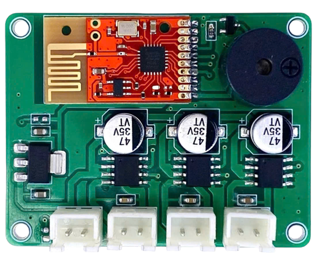
DumbotRX is a versatile receiver module designed for robotics and remote control applications. It is engineered to receive signals from a compatible transmitter and relay them to a microcontroller for further processing. This component is widely used in projects involving wireless communication, such as remote-controlled robots, drones, and other IoT devices. Its compact design and reliable performance make it a popular choice for hobbyists and professionals alike.
Explore Projects Built with DumbotRX
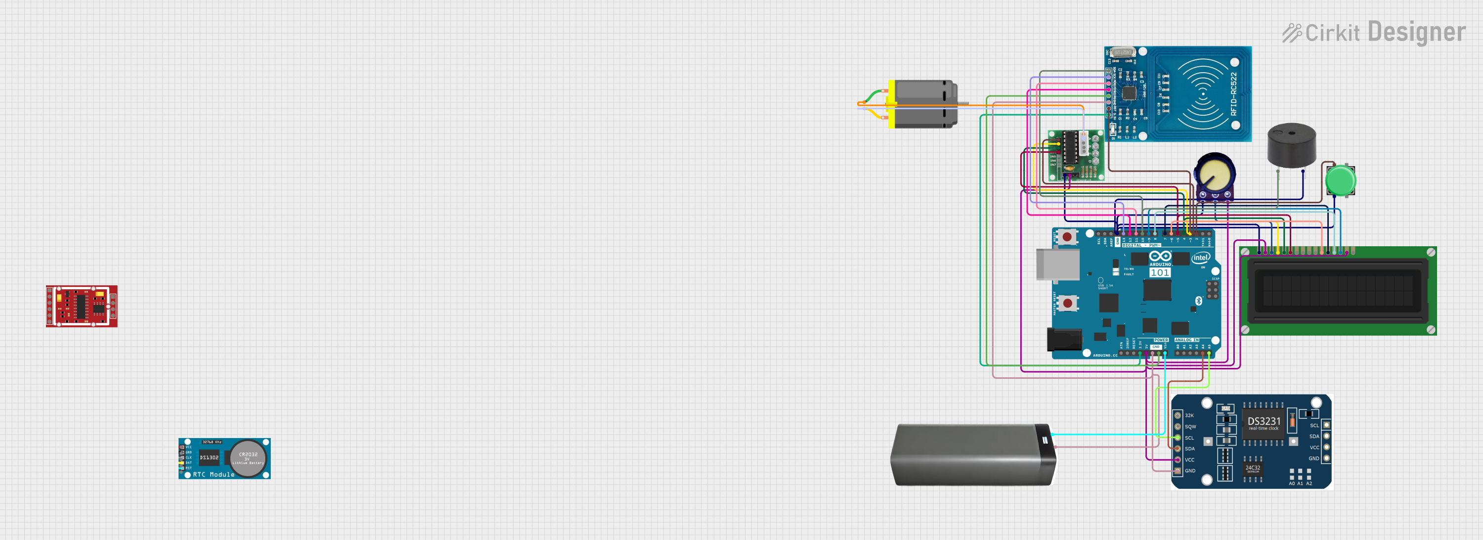
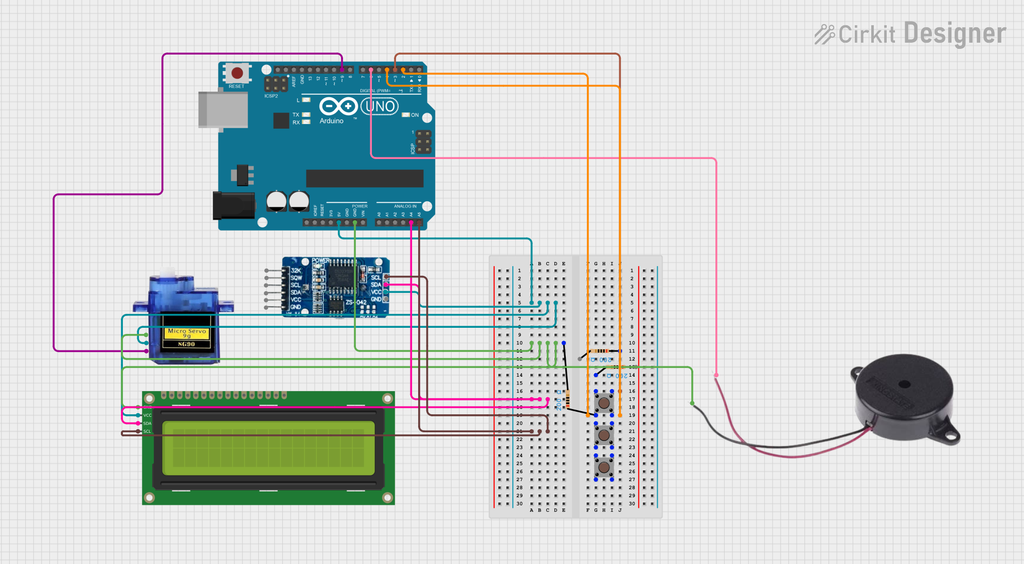
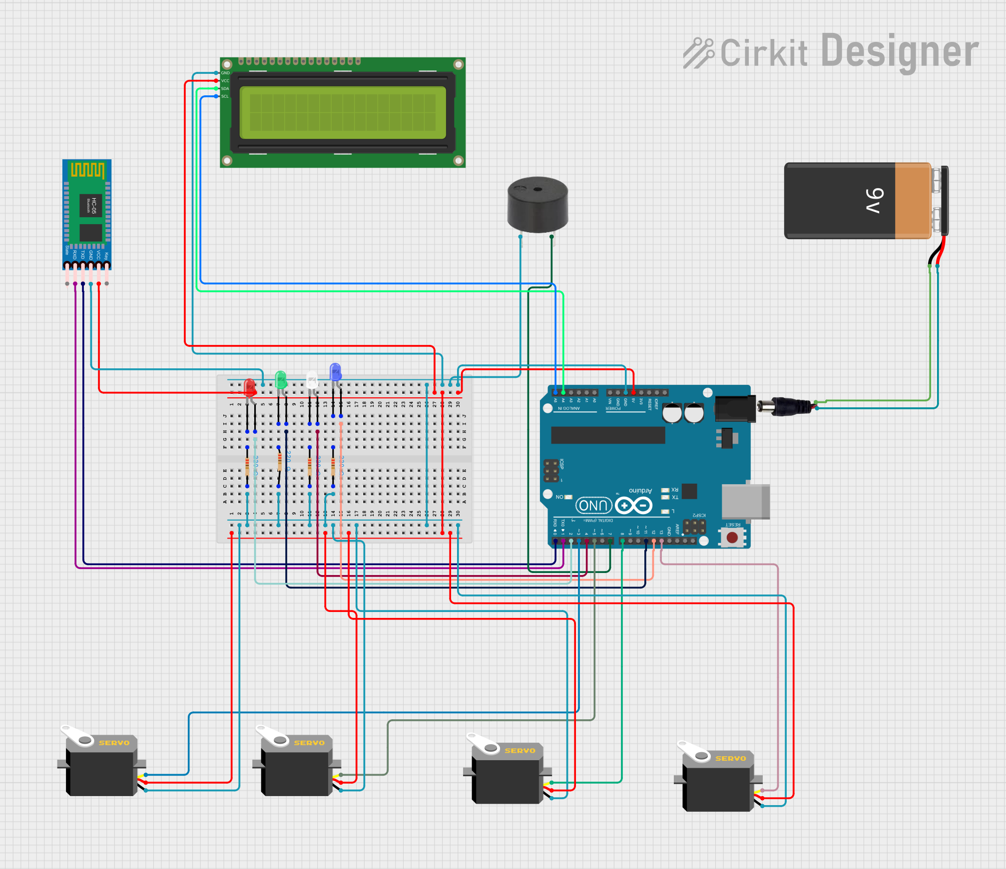
Explore Projects Built with DumbotRX
Common Applications and Use Cases
- Remote-controlled robots and vehicles
- Wireless communication in IoT devices
- Signal reception for drones and UAVs
- Home automation systems
- Wireless data transmission in embedded systems
Technical Specifications
Below are the key technical details of the DumbotRX module:
| Parameter | Specification |
|---|---|
| Operating Voltage | 3.3V to 5V |
| Operating Current | 10mA (typical) |
| Frequency Range | 433 MHz |
| Communication Protocol | Serial (UART) |
| Data Rate | Up to 9600 bps |
| Range | Up to 100 meters (line of sight) |
| Dimensions | 25mm x 15mm x 5mm |
Pin Configuration and Descriptions
The DumbotRX module has 4 pins, as described in the table below:
| Pin | Name | Description |
|---|---|---|
| 1 | VCC | Power supply input (3.3V to 5V). Connect to the power source of your circuit. |
| 2 | GND | Ground. Connect to the ground of your circuit. |
| 3 | DATA | Data output pin. Outputs the received signal to the microcontroller. |
| 4 | ANT | Antenna pin. Connect to an external antenna for improved signal reception. |
Usage Instructions
How to Use the DumbotRX in a Circuit
- Powering the Module: Connect the VCC pin to a 3.3V or 5V power source and the GND pin to the ground of your circuit.
- Connecting to a Microcontroller:
- Connect the DATA pin to a UART-compatible input pin on your microcontroller.
- Ensure the microcontroller's UART baud rate matches the DumbotRX's data rate (default: 9600 bps).
- Antenna Setup: Attach an external antenna to the ANT pin to maximize the signal reception range.
- Programming the Microcontroller: Write code to read the data received on the UART pin and process it as needed.
Important Considerations and Best Practices
- Power Supply: Ensure a stable power supply to avoid signal interruptions.
- Antenna Placement: Place the antenna in an open area, away from metal objects, to reduce interference.
- Signal Range: The module performs best in line-of-sight conditions. Obstacles like walls may reduce the effective range.
- Baud Rate Matching: Always configure the microcontroller's UART baud rate to match the DumbotRX's data rate.
Example Code for Arduino UNO
Below is an example of how to use the DumbotRX module with an Arduino UNO:
// Example code to read data from the DumbotRX module using Arduino UNO

// Define the pin connected to the DATA pin of DumbotRX
#define RX_PIN 2

void setup() {
  // Initialize serial communication for debugging
  Serial.begin(9600);

  // Initialize the pin connected to DumbotRX as an input
  pinMode(RX_PIN, INPUT);

  // Print a message to indicate setup is complete
  Serial.println("DumbotRX setup complete. Waiting for data...");
}

void loop() {
  // Check if data is available on the RX_PIN
  if (digitalRead(RX_PIN) == HIGH) {
    // Read the data from the DumbotRX module
    int receivedData = Serial.read();

    // Print the received data to the Serial Monitor
    Serial.print("Received Data: ");
    Serial.println(receivedData);
  }

  // Add a small delay to avoid overwhelming the serial monitor
  delay(100);
}
Troubleshooting and FAQs
Common Issues and Solutions
No Data Received:
- Ensure the transmitter is powered and functioning correctly.
- Verify that the antenna is properly connected to the ANT pin.
- Check the wiring between the DumbotRX and the microcontroller.
Intermittent Signal Loss:
- Ensure the power supply is stable and within the specified voltage range.
- Minimize interference by keeping the module away from other electronic devices.
Short Range:
- Use a higher-quality antenna or reposition the antenna for better line-of-sight communication.
- Check for obstacles that may block the signal.
Incorrect Data:
- Verify that the microcontroller's UART baud rate matches the DumbotRX's data rate.
- Ensure the transmitter and receiver are operating on the same frequency.
FAQs
Q: Can I use the DumbotRX with a 3.3V microcontroller?
A: Yes, the DumbotRX is compatible with both 3.3V and 5V systems.
Q: What type of antenna should I use with the DumbotRX?
A: A simple wire antenna or a commercially available 433 MHz antenna will work. Ensure the antenna is properly tuned for the frequency.
Q: Can I use multiple DumbotRX modules in the same area?
A: Yes, but ensure that each transmitter-receiver pair operates on a unique identifier or protocol to avoid interference.
Q: How do I increase the range of the DumbotRX?
A: Use a high-gain antenna and ensure a clear line of sight between the transmitter and receiver.