How to Use 8x32 max7219: Examples, Pinouts, and Specs
Introduction
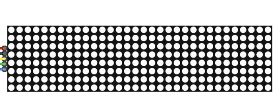
The MAX7219 is a compact, serial input/output common-cathode display driver designed to control up to 64 individual LEDs or 8 digits of a 7-segment display. The 8x32 configuration refers to a matrix of 8 rows and 32 columns, making it ideal for creating LED signage, scrolling text displays, and visual indicators. This component simplifies the process of controlling large LED arrays by reducing the number of required microcontroller pins and providing an easy-to-use serial interface.
Explore Projects Built with 8x32 max7219


Explore Projects Built with 8x32 max7219
Common Applications
- LED signage and scrolling text displays
- Digital clocks and counters
- Visual indicators for industrial or consumer electronics
- Gaming devices and scoreboards
- Educational projects and prototyping
Technical Specifications
The MAX7219 is a versatile and efficient display driver with the following key specifications:
| Parameter | Value |
|---|---|
| Operating Voltage | 4.0V to 5.5V |
| Maximum Current | 320mA (typical for full load) |
| Communication Interface | Serial (SPI-compatible) |
| LED Matrix Configuration | 8 rows x 32 columns |
| Maximum LED Control | 64 LEDs or 8 digits of 7-segment |
| Operating Temperature | -40°C to +85°C |
Pin Configuration and Descriptions
The MAX7219 module typically has the following pinout:
| Pin Name | Pin Number | Description |
|---|---|---|
| VCC | 1 | Power supply input (4.0V to 5.5V). Connect to the 5V pin of your microcontroller. |
| GND | 2 | Ground connection. Connect to the ground of your circuit. |
| DIN | 3 | Serial data input. Used to send data to the MAX7219. |
| CS | 4 | Chip select. Active low; used to enable communication with the MAX7219. |
| CLK | 5 | Serial clock input. Synchronizes data transfer with the microcontroller. |
Usage Instructions
How to Use the MAX7219 in a Circuit
- Power the Module: Connect the VCC pin to a 5V power source and the GND pin to the ground.
- Connect to Microcontroller: Use the SPI interface to connect the DIN, CS, and CLK pins to the corresponding pins on your microcontroller.
- Load the Required Library: If using an Arduino, install the
LedControllibrary, which simplifies communication with the MAX7219. - Initialize the Module: Use the library functions to initialize the MAX7219 and configure the display settings.
- Send Data: Use the library to send data to the display, such as characters, numbers, or patterns.
Important Considerations and Best Practices
- Current Limiting: The MAX7219 includes internal current limiting, but ensure your power supply can handle the total current draw of the LEDs.
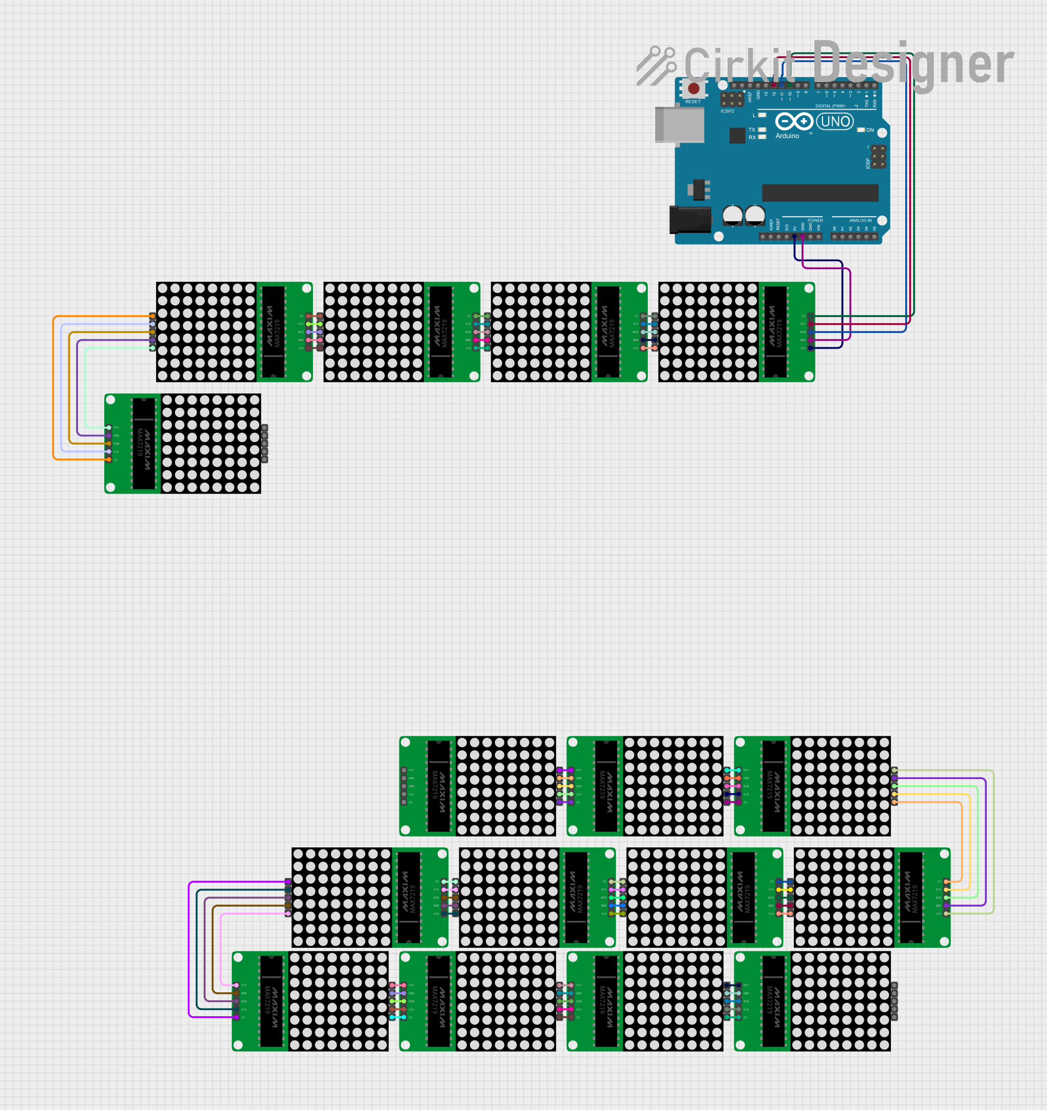
- Daisy-Chaining: Multiple MAX7219 modules can be daisy-chained to control larger displays. Connect the DOUT pin of one module to the DIN pin of the next.
- Decoupling Capacitor: Place a 10µF electrolytic capacitor and a 0.1µF ceramic capacitor across the VCC and GND pins to stabilize the power supply.
- Brightness Control: Use the intensity control register to adjust the brightness of the LEDs.
Example Code for Arduino UNO
Below is an example of how to use the MAX7219 with an Arduino UNO to display scrolling text:
#include <LedControl.h>

// Initialize the LedControl library
// Parameters: DIN pin, CLK pin, CS pin, number of MAX7219 modules
LedControl lc = LedControl(12, 11, 10, 1);

void setup() {
  // Initialize the MAX7219 module
  lc.shutdown(0, false);  // Wake up the display
  lc.setIntensity(0, 8);  // Set brightness level (0-15)
  lc.clearDisplay(0);     // Clear the display
}

void loop() {
  // Display scrolling text
  char message[] = "HELLO WORLD ";
  for (int i = 0; i < strlen(message) * 8; i++) {
    lc.clearDisplay(0);  // Clear the display
    for (int j = 0; j < 8; j++) {
      // Shift the message to create a scrolling effect
      lc.setRow(0, j, pgm_read_byte_near(font8x8[message[(i + j) % strlen(message)]]));
    }
    delay(100);  // Adjust scrolling speed
  }
}

// Font data for 8x8 characters (example for 'H', 'E', 'L', 'O', etc.)
// Add the full font data as needed
const byte font8x8[][8] PROGMEM = {
  {0x00, 0x7E, 0x09, 0x09, 0x7E, 0x00, 0x00, 0x00}, // H
  {0x00, 0x7F, 0x49, 0x49, 0x41, 0x00, 0x00, 0x00}, // E
  {0x00, 0x7F, 0x01, 0x01, 0x01, 0x00, 0x00, 0x00}, // L
  {0x00, 0x3E, 0x41, 0x41, 0x3E, 0x00, 0x00, 0x00}, // O
};
Notes:
- Replace the
font8x8array with a complete font set for all characters you want to display. - Adjust the
delay()value to control the scrolling speed.
Troubleshooting and FAQs
Common Issues
No Display Output:
- Ensure the VCC and GND connections are secure.
- Verify that the DIN, CS, and CLK pins are correctly connected to the microcontroller.
- Check the power supply voltage (should be 5V).
Flickering LEDs:
- Add decoupling capacitors across the VCC and GND pins.
- Ensure the power supply can handle the current requirements of the LEDs.
Incorrect or Garbled Display:
- Verify the SPI communication settings (e.g., clock speed and data order).
- Check for loose or incorrect wiring.
Brightness Too Low:
- Use the intensity control register to increase the brightness level.
- Ensure the power supply is not overloaded.
FAQs
Q: Can I daisy-chain multiple MAX7219 modules?
A: Yes, you can daisy-chain multiple modules by connecting the DOUT pin of one module to the DIN pin of the next. Update the LedControl initialization to reflect the total number of modules.
Q: How do I control individual LEDs in the matrix?
A: Use the setLed() function in the LedControl library to turn individual LEDs on or off.
Q: What is the maximum number of modules I can daisy-chain?
A: Theoretically, you can daisy-chain up to 8 modules, but performance may degrade with more modules due to signal attenuation.
Q: Can I use a 3.3V microcontroller with the MAX7219?
A: The MAX7219 requires a 5V power supply, but it can accept 3.3V logic levels for the DIN, CS, and CLK pins. Use level shifters if needed for reliable operation.