How to Use TMP117: Examples, Pinouts, and Specs
Introduction
The TMP117 is a high-accuracy digital temperature sensor designed to provide precise temperature readings with a resolution of 0.1°C. It features an I2C interface, enabling seamless integration with microcontroller-based systems. The TMP117 operates over a wide temperature range of -55°C to +150°C, making it suitable for a variety of applications, including industrial monitoring, medical devices, HVAC systems, and consumer electronics.
Explore Projects Built with TMP117


Explore Projects Built with TMP117
Common Applications
- Industrial temperature monitoring
- Medical devices requiring precise temperature measurements
- HVAC systems for environmental control
- Consumer electronics for thermal management
- IoT devices and data loggers
Technical Specifications
Key Technical Details
| Parameter | Value |
|---|---|
| Supply Voltage (VDD) | 1.8V to 5.5V |
| Temperature Range | -55°C to +150°C |
| Temperature Accuracy | ±0.1°C (typical, -20°C to +50°C) |
| Resolution | 0.0078°C |
| Interface | I2C (up to 400 kHz) |
| Current Consumption | 3.5 µA (typical, 1 Hz sampling) |
| Package | WSON-6 (2.0 mm × 2.0 mm) |
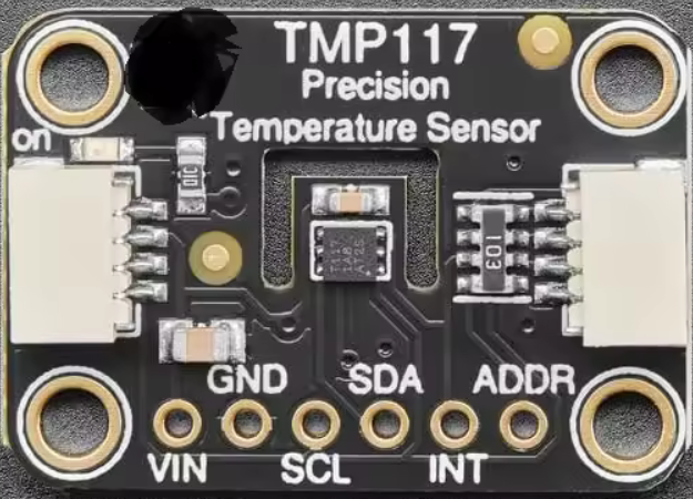
Pin Configuration and Descriptions
The TMP117 comes in a 6-pin WSON package. Below is the pinout description:
| Pin Number | Pin Name | Description |
|---|---|---|
| 1 | VDD | Power supply input (1.8V to 5.5V) |
| 2 | GND | Ground |
| 3 | SDA | I2C data line |
| 4 | SCL | I2C clock line |
| 5 | ALERT | Alert output (active low) |
| 6 | ADD0 | I2C address selection |
Usage Instructions
How to Use the TMP117 in a Circuit
- Power Supply: Connect the VDD pin to a regulated power supply (1.8V to 5.5V) and the GND pin to ground.
- I2C Interface: Connect the SDA and SCL pins to the corresponding I2C data and clock lines of your microcontroller. Use pull-up resistors (typically 4.7 kΩ) on both lines.
- Address Selection: Use the ADD0 pin to configure the I2C address. Tie it to GND or VDD to select one of two possible addresses.
- Alert Pin: Optionally, connect the ALERT pin to monitor temperature threshold events.
Important Considerations
- Ensure proper decoupling by placing a 0.1 µF capacitor close to the VDD pin.
- Avoid placing the sensor near heat sources to prevent inaccurate readings.
- Use appropriate pull-up resistors for the I2C lines to ensure reliable communication.
- The TMP117 supports standard and fast I2C modes (up to 400 kHz).
Example Code for Arduino UNO
Below is an example of how to interface the TMP117 with an Arduino UNO using the Wire library:
#include <Wire.h>

#define TMP117_ADDRESS 0x48 // Default I2C address when ADD0 is tied to GND
#define TEMP_RESULT_REG 0x00 // Register for temperature result

void setup() {
  Wire.begin(); // Initialize I2C communication
  Serial.begin(9600); // Start serial communication for debugging

  // Check if TMP117 is connected
  Wire.beginTransmission(TMP117_ADDRESS);
  if (Wire.endTransmission() != 0) {
    Serial.println("TMP117 not detected. Check connections.");
    while (1); // Halt execution if sensor is not found
  }
  Serial.println("TMP117 detected successfully.");
}

void loop() {
  float temperature = readTemperature();
  Serial.print("Temperature: ");
  Serial.print(temperature);
  Serial.println(" °C");
  delay(1000); // Wait 1 second before the next reading
}

float readTemperature() {
  Wire.beginTransmission(TMP117_ADDRESS);
  Wire.write(TEMP_RESULT_REG); // Point to the temperature result register
  Wire.endTransmission();

  Wire.requestFrom(TMP117_ADDRESS, 2); // Request 2 bytes of data
  if (Wire.available() == 2) {
    int16_t rawData = (Wire.read() << 8) | Wire.read(); // Combine MSB and LSB
    return rawData * 0.0078125; // Convert to Celsius (0.0078125°C/LSB)
  } else {
    Serial.println("Error reading temperature.");
    return NAN; // Return NaN if data is unavailable
  }
}
Troubleshooting and FAQs
Common Issues and Solutions
TMP117 Not Detected on I2C Bus:
- Verify the wiring, especially the SDA and SCL connections.
- Ensure pull-up resistors are present on the I2C lines.
- Check the ADD0 pin configuration to confirm the correct I2C address.
Inaccurate Temperature Readings:
- Ensure the sensor is not placed near heat sources or in direct sunlight.
- Verify the power supply voltage is within the specified range (1.8V to 5.5V).
- Check for proper decoupling with a 0.1 µF capacitor near the VDD pin.
I2C Communication Errors:
- Confirm the I2C clock speed does not exceed 400 kHz.
- Check for loose or faulty connections in the circuit.
FAQs
Q: Can the TMP117 operate at 3.3V?
A: Yes, the TMP117 operates within a supply voltage range of 1.8V to 5.5V, so 3.3V is within the acceptable range.
Q: How do I set temperature thresholds for the ALERT pin?
A: The TMP117 allows you to configure high and low temperature thresholds via specific registers. Refer to the TMP117 datasheet for details on programming these registers.
Q: What is the default I2C address of the TMP117?
A: The default I2C address is 0x48 when the ADD0 pin is tied to GND. If ADD0 is tied to VDD, the address changes to 0x49.