How to Use Two Color LED: Examples, Pinouts, and Specs
Introduction
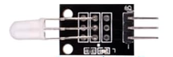
A Two Color LED is a light-emitting diode capable of emitting two distinct colors of light. This is typically achieved by incorporating two separate LED chips within a single package or by altering the polarity of the current flowing through the LED. These LEDs are widely used in applications where status indication or multi-state signaling is required, such as in electronic devices, control panels, and DIY projects.
Explore Projects Built with Two Color LED

Explore Projects Built with Two Color LED
Common Applications and Use Cases
- Status indicators (e.g., power on/off, error states)
- Multi-state signaling in control systems
- Visual feedback in user interfaces
- DIY electronics and hobby projects
- Automotive dashboards and displays
Technical Specifications
Key Technical Details
- Forward Voltage (per LED chip): 1.8V to 3.3V (varies by color)
- Forward Current (per LED chip): 20mA (typical)
- Colors: Commonly red and green, but other combinations are available
- Polarity Control: Color changes based on the direction of current flow
- Package Type: 2-pin or 3-pin configurations
- Viewing Angle: 20° to 60° (varies by model)
- Operating Temperature Range: -40°C to +85°C
Pin Configuration and Descriptions
2-Pin Two Color LED
| Pin Number | Name | Description |
|---|---|---|
| 1 | Anode/Cathode | Acts as the positive terminal for one color and the negative terminal for the other color. |
| 2 | Cathode/Anode | Acts as the negative terminal for one color and the positive terminal for the other color. |
3-Pin Two Color LED
| Pin Number | Name | Description |
|---|---|---|
| 1 | Anode 1 | Positive terminal for the first LED chip (e.g., red). |
| 2 | Common Cathode/Anode | Shared negative or positive terminal for both LED chips. |
| 3 | Anode 2 | Positive terminal for the second LED chip (e.g., green). |
Usage Instructions
How to Use the Component in a Circuit
- Determine the LED Type: Identify whether the Two Color LED is a 2-pin or 3-pin type.
- Connect the LED:
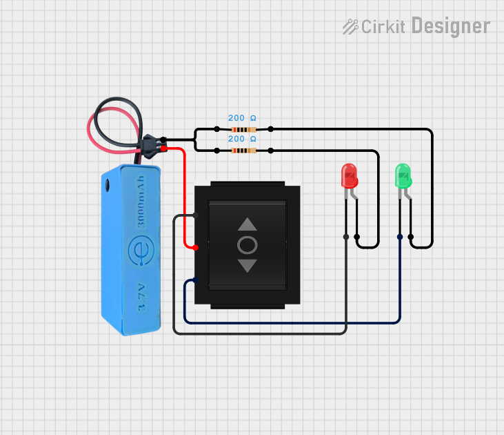
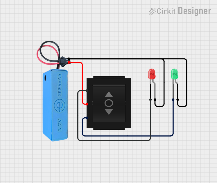
- For a 2-pin LED, connect the pins to a DC power source with a current-limiting resistor (typically 220Ω to 1kΩ). Reverse the polarity to switch between colors.
- For a 3-pin LED, connect the common pin to the appropriate voltage (ground for common cathode or Vcc for common anode). Use separate current-limiting resistors for each anode pin.
- Control the LED:
- Use a microcontroller (e.g., Arduino) or a manual switch to control the current flow and select the desired color.
Important Considerations and Best Practices
- Always use a current-limiting resistor to prevent damage to the LED.
- Verify the forward voltage and current ratings for each color before connecting the LED.
- For 2-pin LEDs, ensure the power supply polarity is correct to avoid malfunction.
- For 3-pin LEDs, ensure the common pin is correctly connected to ground or Vcc based on the LED type.
- Avoid exceeding the maximum forward current to prolong the LED's lifespan.
Example: Connecting a 2-Pin Two Color LED to an Arduino UNO
// Example code to control a 2-pin Two Color LED with an Arduino UNO
// Connect one pin of the LED to pin 9 and the other to pin 10 via 220Ω resistors.

const int ledPin1 = 9; // Pin connected to one side of the LED
const int ledPin2 = 10; // Pin connected to the other side of the LED

void setup() {
  pinMode(ledPin1, OUTPUT); // Set pin 9 as an output
  pinMode(ledPin2, OUTPUT); // Set pin 10 as an output
}

void loop() {
  digitalWrite(ledPin1, HIGH); // Turn on the first color
  digitalWrite(ledPin2, LOW);  // Ensure the second color is off
  delay(1000); // Wait for 1 second

  digitalWrite(ledPin1, LOW);  // Turn off the first color
  digitalWrite(ledPin2, HIGH); // Turn on the second color
  delay(1000); // Wait for 1 second
}
Troubleshooting and FAQs
Common Issues and Solutions
LED Does Not Light Up:
- Check the polarity of the connections. Reverse the connections if using a 2-pin LED.
- Ensure the current-limiting resistor is not too large, which could prevent sufficient current flow.
- Verify the power supply voltage matches the LED's forward voltage requirements.
LED Flickers or is Dim:
- Check for loose connections or poor soldering.
- Ensure the power supply provides a stable voltage and current.
One Color Does Not Work:
- Verify the connections for the non-working color.
- Test the LED with a multimeter to check if one of the LED chips is damaged.
LED Overheats:
- Ensure the current-limiting resistor is appropriately sized to limit the current to 20mA or less.
- Avoid prolonged operation at maximum current.
FAQs
Q: Can I use a Two Color LED without a resistor?
A: No, a current-limiting resistor is essential to prevent excessive current, which can damage the LED.
Q: How do I identify the common pin on a 3-pin Two Color LED?
A: Use a multimeter in diode mode to test the connections. The common pin will show continuity with both anodes (or cathodes) depending on the LED type.
Q: Can I control a Two Color LED with PWM?
A: Yes, you can use PWM (Pulse Width Modulation) to control the brightness of each color independently, especially with a 3-pin LED.
Q: What happens if I reverse the polarity of a 2-pin Two Color LED?
A: The LED will emit the second color, as the current flows through the other LED chip.