How to Use DFRobot DFR0971 GP8403 0-5V/10V 12-bit: Examples, Pinouts, and Specs
Introduction
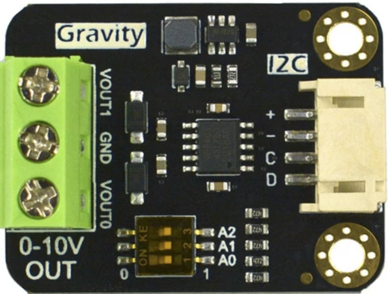
The DFRobot DFR0971 GP8403 is a high-precision analog-to-digital converter (ADC) designed to convert analog signals into digital data with 12-bit resolution. It supports input voltage ranges of 0-5V or 0-10V, making it ideal for interfacing with a wide variety of sensors and analog devices. This component is particularly useful in applications requiring accurate signal measurement and processing, such as industrial automation, environmental monitoring, and IoT systems.
Explore Projects Built with DFRobot DFR0971 GP8403 0-5V/10V 12-bit


Explore Projects Built with DFRobot DFR0971 GP8403 0-5V/10V 12-bit
Common Applications and Use Cases
- Sensor data acquisition (e.g., temperature, pressure, or light sensors)
- Industrial control systems
- Data logging and monitoring
- IoT devices requiring high-precision analog signal conversion
- Robotics and automation systems
Technical Specifications
The following table outlines the key technical details of the DFRobot DFR0971 GP8403 ADC:
| Parameter | Specification |
|---|---|
| Input Voltage Range | 0-5V or 0-10V (selectable) |
| Resolution | 12-bit (4096 levels) |
| Communication Interface | I2C |
| Operating Voltage | 3.3V or 5V |
| Operating Current | < 5mA |
| Sampling Rate | Up to 240 samples per second |
| Dimensions | 22mm x 30mm |
| Operating Temperature | -40°C to 85°C |
Pin Configuration and Descriptions
The DFR0971 module has a simple pinout for easy integration into circuits. The table below describes each pin:
| Pin | Name | Description |
|---|---|---|
| 1 | VCC | Power supply input (3.3V or 5V) |
| 2 | GND | Ground connection |
| 3 | SDA | I2C data line for communication |
| 4 | SCL | I2C clock line for communication |
| 5 | A0 | Analog input channel 0 (supports 0-5V or 0-10V, depending on configuration) |
| 6 | A1 | Analog input channel 1 (supports 0-5V or 0-10V, depending on configuration) |
| 7 | ADDR | I2C address selection pin (used to set the I2C address of the module) |
Usage Instructions
How to Use the Component in a Circuit
- Power Supply: Connect the
VCCpin to a 3.3V or 5V power source and theGNDpin to ground. - I2C Communication: Connect the
SDAandSCLpins to the corresponding I2C pins on your microcontroller (e.g., Arduino UNO). - Analog Inputs: Connect the analog signals to the
A0and/orA1pins. Ensure the input voltage does not exceed the selected range (0-5V or 0-10V). - I2C Address Configuration: Use the
ADDRpin to set the I2C address if multiple DFR0971 modules are used in the same circuit. - Voltage Range Selection: Configure the input voltage range (0-5V or 0-10V) using the onboard jumper or configuration settings.
Important Considerations and Best Practices
- Input Voltage Range: Ensure the input voltage does not exceed the selected range to avoid damaging the module.
- I2C Pull-Up Resistors: If your microcontroller does not have built-in pull-up resistors on the I2C lines, add external pull-up resistors (typically 4.7kΩ) to the
SDAandSCLlines. - Noise Reduction: To minimize noise, use short and shielded wires for the analog input signals.
- Power Supply Stability: Use a stable and noise-free power supply to ensure accurate ADC readings.
Example Code for Arduino UNO
The following example demonstrates how to read analog data from the DFR0971 using an Arduino UNO:
#include <Wire.h>

// I2C address of the DFR0971 module (default: 0x48)
#define DFR0971_I2C_ADDRESS 0x48

void setup() {
  Wire.begin(); // Initialize I2C communication
  Serial.begin(9600); // Initialize serial communication for debugging
  Serial.println("DFR0971 ADC Example");
}

void loop() {
  uint16_t adcValue = readADC(0); // Read from channel 0
  float voltage = (adcValue / 4095.0) * 5.0; // Convert to voltage (0-5V range)

  Serial.print("ADC Value: ");
  Serial.print(adcValue);
  Serial.print(" | Voltage: ");
  Serial.print(voltage, 3); // Print voltage with 3 decimal places
  Serial.println(" V");

  delay(500); // Wait 500ms before the next reading
}

// Function to read ADC value from a specific channel
uint16_t readADC(uint8_t channel) {
  Wire.beginTransmission(DFR0971_I2C_ADDRESS);
  Wire.write(channel); // Send the channel number (0 or 1)
  Wire.endTransmission();

  Wire.requestFrom(DFR0971_I2C_ADDRESS, 2); // Request 2 bytes of data
  if (Wire.available() == 2) {
    uint8_t highByte = Wire.read(); // Read the high byte
    uint8_t lowByte = Wire.read();  // Read the low byte
    return (highByte << 8) | lowByte; // Combine the two bytes into a 12-bit value
  }
  return 0; // Return 0 if no data is available
}
Troubleshooting and FAQs
Common Issues and Solutions
No Data from the ADC
- Cause: Incorrect I2C wiring or address mismatch.
- Solution: Verify the
SDAandSCLconnections and ensure the I2C address matches the module's configuration.
Inaccurate Readings
- Cause: Noise in the analog input signal or unstable power supply.
- Solution: Use shielded cables for analog inputs and ensure a stable power source.
Module Not Detected
- Cause: Missing pull-up resistors on the I2C lines.
- Solution: Add 4.7kΩ pull-up resistors to the
SDAandSCLlines.
Voltage Range Misconfiguration
- Cause: Incorrect jumper setting for the input voltage range.
- Solution: Check and adjust the jumper to match the desired range (0-5V or 0-10V).
FAQs
Can I use this module with a 3.3V microcontroller?
- Yes, the DFR0971 supports both 3.3V and 5V logic levels.
How do I change the I2C address?
- Use the
ADDRpin to set a different I2C address. Refer to the module's datasheet for address configuration details.
- Use the
What is the maximum sampling rate?
- The module supports a maximum sampling rate of 240 samples per second.
Can I use both analog channels simultaneously?
- Yes, you can read from both
A0andA1channels sequentially using the I2C interface.
- Yes, you can read from both