How to Use MITSUBISHI CP30-BA 5A: Examples, Pinouts, and Specs
Introduction
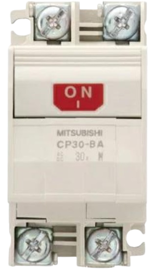
The MITSUBISHI CP30-BA 5A is a compact relay designed for controlling electrical circuits, capable of handling up to 5A of current. This relay is widely used in automation and control systems for switching applications, offering reliable performance in industrial and commercial environments. Its compact design makes it suitable for space-constrained installations, while its robust construction ensures durability and long-term operation.
Explore Projects Built with MITSUBISHI CP30-BA 5A


Explore Projects Built with MITSUBISHI CP30-BA 5A
Common Applications and Use Cases
- Industrial automation systems
- Motor control circuits
- HVAC systems
- Lighting control
- Power distribution panels
- Safety and protection circuits
Technical Specifications
The following table outlines the key technical details of the MITSUBISHI CP30-BA 5A:
| Parameter | Specification |
|---|---|
| Manufacturer | Mitsubishi Electric |
| Model Number | CP30-BA 5A |
| Rated Current | 5A |
| Rated Voltage | 250V AC / 30V DC |
| Contact Configuration | SPST (Single Pole Single Throw) |
| Operating Temperature | -10°C to 55°C |
| Insulation Resistance | ≥ 100 MΩ (at 500V DC) |
| Dielectric Strength | 2000V AC for 1 minute |
| Dimensions | Compact form factor |
| Mounting Style | DIN rail or panel mount |
Pin Configuration and Descriptions
The MITSUBISHI CP30-BA 5A relay features a simple pin configuration for easy integration into circuits. The table below describes the pin layout:
| Pin Number | Description |
|---|---|
| 1 | Input Terminal (Live/Hot) |
| 2 | Input Terminal (Neutral) |
| 3 | Output Terminal (Normally Open) |
| 4 | Output Terminal (Common) |
Usage Instructions
How to Use the Component in a Circuit
- Power Supply Connection: Connect the input terminals (Pin 1 and Pin 2) to the appropriate power source. Ensure the voltage and current ratings do not exceed the specified limits.
- Load Connection: Connect the load to the output terminals (Pin 3 and Pin 4). The relay will control the flow of current to the load.
- Control Signal: Use an external control signal to activate the relay. This can be achieved using a microcontroller, switch, or other control devices.
- Mounting: Secure the relay to a DIN rail or panel mount as per the installation requirements.
Important Considerations and Best Practices
- Voltage and Current Ratings: Do not exceed the rated voltage (250V AC / 30V DC) or current (5A) to avoid damage to the relay.
- Proper Insulation: Ensure proper insulation of all connections to prevent short circuits or electrical hazards.
- Environmental Conditions: Operate the relay within the specified temperature range (-10°C to 55°C) for optimal performance.
- Testing: Test the relay in a controlled environment before deploying it in critical applications.
Example: Connecting to an Arduino UNO
The MITSUBISHI CP30-BA 5A can be controlled using an Arduino UNO. Below is an example circuit and code to toggle the relay using a digital output pin.
Circuit Setup
- Connect the relay's control input to Arduino's digital pin (e.g., Pin 7) through a transistor and a flyback diode for protection.
- Connect the relay's input terminals to a 5V power supply.
- Connect the load to the relay's output terminals.
Arduino Code
// Define the pin connected to the relay
const int relayPin = 7;

void setup() {
  // Set the relay pin as an output
  pinMode(relayPin, OUTPUT);

  // Initialize the relay in the OFF state
  digitalWrite(relayPin, LOW);
}

void loop() {
  // Turn the relay ON
  digitalWrite(relayPin, HIGH);
  delay(1000); // Keep the relay ON for 1 second

  // Turn the relay OFF
  digitalWrite(relayPin, LOW);
  delay(1000); // Keep the relay OFF for 1 second
}
Note: Always use a transistor and a flyback diode when interfacing the relay with a microcontroller to protect the circuit from voltage spikes.
Troubleshooting and FAQs
Common Issues and Solutions
Relay Not Activating:
- Cause: Insufficient control signal voltage or current.
- Solution: Verify the control signal and ensure it meets the relay's activation requirements.
Overheating:
- Cause: Exceeding the rated current or poor ventilation.
- Solution: Ensure the load does not exceed 5A and provide adequate ventilation.
Intermittent Operation:
- Cause: Loose connections or faulty wiring.
- Solution: Check all connections and ensure they are secure.
No Output:
- Cause: Faulty relay or incorrect wiring.
- Solution: Test the relay with a multimeter and verify the wiring.
FAQs
Q1: Can the MITSUBISHI CP30-BA 5A handle DC loads?
A1: Yes, the relay can handle DC loads up to 30V DC at 5A.
Q2: Is the relay suitable for outdoor use?
A2: The relay is not specifically designed for outdoor use. If used outdoors, ensure it is housed in a weatherproof enclosure.
Q3: Can I use this relay with a 12V control signal?
A3: Yes, but ensure the control circuit is designed to provide sufficient current to activate the relay.
Q4: What is the lifespan of the relay?
A4: The relay's lifespan depends on the load and operating conditions. Under normal conditions, it can last for thousands of switching cycles.