How to Use ESP32: Examples, Pinouts, and Specs
Introduction
The ESP32 is a low-cost, low-power system on a chip (SoC) developed by Espressif Systems. It features integrated Wi-Fi and Bluetooth capabilities, making it an ideal choice for Internet of Things (IoT) applications, smart devices, and embedded systems. With its dual-core processor, extensive GPIO options, and support for various communication protocols, the ESP32 is a versatile and powerful microcontroller for a wide range of projects.
Explore Projects Built with ESP32


Explore Projects Built with ESP32
Common Applications and Use Cases
- IoT devices and smart home automation
- Wireless sensor networks
- Wearable electronics
- Industrial automation
- Robotics and drones
- Real-time data monitoring and logging
Technical Specifications
The ESP32 is packed with features that make it suitable for both simple and complex applications. Below are its key technical specifications:
General Specifications
| Feature | Description |
|---|---|
| Processor | Dual-core Xtensa® 32-bit LX6 microprocessor |
| Clock Speed | Up to 240 MHz |
| Flash Memory | 4 MB (varies by model) |
| SRAM | 520 KB |
| Wireless Connectivity | Wi-Fi 802.11 b/g/n, Bluetooth 4.2 (Classic + BLE) |
| Operating Voltage | 3.3V |
| GPIO Pins | Up to 34 GPIO pins |
| ADC Channels | 18 (12-bit resolution) |
| DAC Channels | 2 (8-bit resolution) |
| Communication Interfaces | UART, SPI, I2C, I2S, CAN, PWM |
| Power Consumption | Ultra-low power modes available |
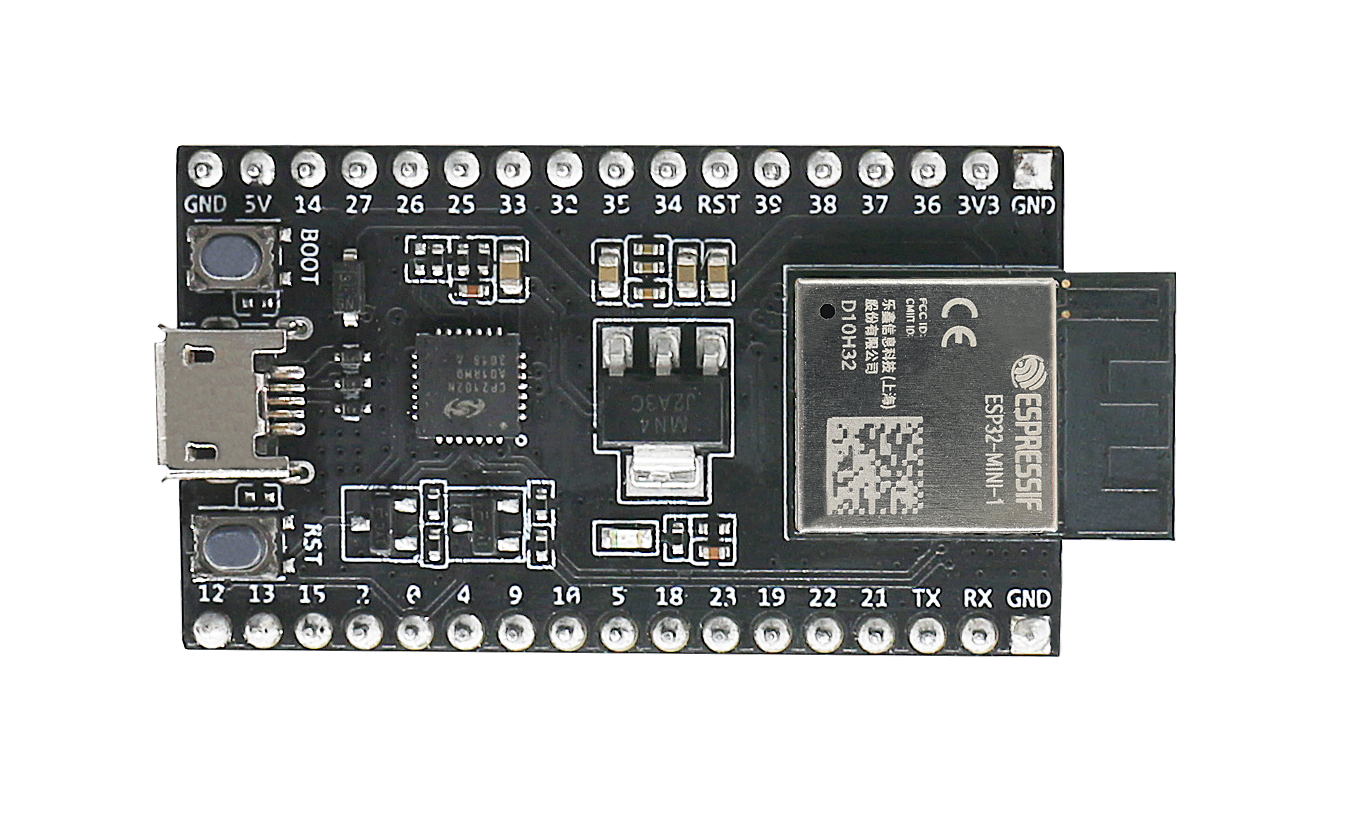
Pin Configuration and Descriptions
The ESP32 has multiple variants, but the following table outlines the general pin configuration for the ESP32 DevKit module:
| Pin Name | Pin Number | Description |
|---|---|---|
| VIN | 1 | Input power (5V) |
| GND | 2, 3 | Ground |
| GPIO0 | 4 | General-purpose I/O, boot mode selection |
| GPIO2 | 5 | General-purpose I/O, supports ADC and PWM |
| GPIO4 | 6 | General-purpose I/O, supports ADC and PWM |
| GPIO5 | 7 | General-purpose I/O, supports ADC and PWM |
| GPIO12 | 8 | General-purpose I/O, supports ADC and PWM |
| GPIO13 | 9 | General-purpose I/O, supports ADC and PWM |
| GPIO14 | 10 | General-purpose I/O, supports ADC and PWM |
| GPIO15 | 11 | General-purpose I/O, supports ADC and PWM |
| EN | 12 | Enable pin, used to reset the chip |
| TX0 | 13 | UART0 Transmit |
| RX0 | 14 | UART0 Receive |
Note: The exact pinout may vary depending on the ESP32 module or development board you are using. Always refer to the datasheet for your specific model.
Usage Instructions
How to Use the ESP32 in a Circuit
- Powering the ESP32: Connect the VIN pin to a 5V power source or use the micro-USB port on the development board. Ensure the GND pin is connected to the ground of your circuit.
- Programming the ESP32: Use the Arduino IDE or Espressif's ESP-IDF framework to write and upload code. The ESP32 can be programmed via its USB interface.
- Connecting Peripherals: Use the GPIO pins to connect sensors, actuators, or other peripherals. Ensure the voltage levels are compatible (3.3V logic).
- Wi-Fi and Bluetooth Setup: Configure the Wi-Fi or Bluetooth settings in your code to enable wireless communication.
Important Considerations and Best Practices
- Voltage Levels: The ESP32 operates at 3.3V logic. Avoid connecting 5V signals directly to its GPIO pins.
- Boot Mode: GPIO0 must be pulled low during boot to enter programming mode.
- Power Supply: Use a stable power source to avoid unexpected resets or instability.
- Heat Management: The ESP32 can get warm during operation. Ensure proper ventilation if used in enclosed spaces.
Example Code for Arduino IDE
Below is an example of how to connect the ESP32 to a Wi-Fi network and blink an LED:
#include <WiFi.h> // Include the Wi-Fi library

const char* ssid = "Your_SSID";       // Replace with your Wi-Fi SSID
const char* password = "Your_Password"; // Replace with your Wi-Fi password
const int ledPin = 2;                 // GPIO2 is typically connected to the onboard LED

void setup() {
  pinMode(ledPin, OUTPUT);            // Set GPIO2 as an output
  Serial.begin(115200);               // Initialize serial communication
  Serial.println("Connecting to Wi-Fi...");

  WiFi.begin(ssid, password);         // Start Wi-Fi connection
  while (WiFi.status() != WL_CONNECTED) {
    delay(500);
    Serial.print(".");
  }
  Serial.println("\nWi-Fi connected!");
  Serial.print("IP Address: ");
  Serial.println(WiFi.localIP());     // Print the ESP32's IP address
}

void loop() {
  digitalWrite(ledPin, HIGH);         // Turn the LED on
  delay(1000);                        // Wait for 1 second
  digitalWrite(ledPin, LOW);          // Turn the LED off
  delay(1000);                        // Wait for 1 second
}
Troubleshooting and FAQs
Common Issues
- ESP32 Not Connecting to Wi-Fi
- Solution: Double-check the SSID and password in your code. Ensure the Wi-Fi network is active and within range.
- Upload Fails with Timeout Error
- Solution: Ensure the ESP32 is in boot mode by holding down the BOOT button while uploading code.
- GPIO Pins Not Responding
- Solution: Verify that the pins are not being used for other functions (e.g., UART, ADC). Check for short circuits or incorrect wiring.
- ESP32 Keeps Resetting
- Solution: Use a stable power supply. Avoid drawing excessive current from the GPIO pins.
FAQs
Q: Can the ESP32 operate on battery power?
A: Yes, the ESP32 can be powered by batteries. Use a 3.7V LiPo battery with a voltage regulator or a 5V power bank.
Q: How do I update the ESP32 firmware?
A: Firmware updates can be performed using the Espressif Flash Download Tool or via OTA (Over-The-Air) updates in your code.
Q: Can I use the ESP32 with 5V sensors?
A: Yes, but you will need a level shifter to convert the 5V signals to 3.3V to avoid damaging the ESP32.
Q: Is the ESP32 compatible with Arduino libraries?
A: Yes, the ESP32 is supported by the Arduino IDE and many Arduino libraries. Install the ESP32 board package in the Arduino IDE to get started.