How to Use PF25-48 Step Motor: Examples, Pinouts, and Specs
Introduction
The PF25-48 Step Motor by NPM is a high-precision stepper motor designed for applications that require accurate positioning and repeatability. This motor is ideal for use in robotics, CNC machines, 3D printers, and other automated systems where precise control of angular position is crucial.
Explore Projects Built with PF25-48 Step Motor
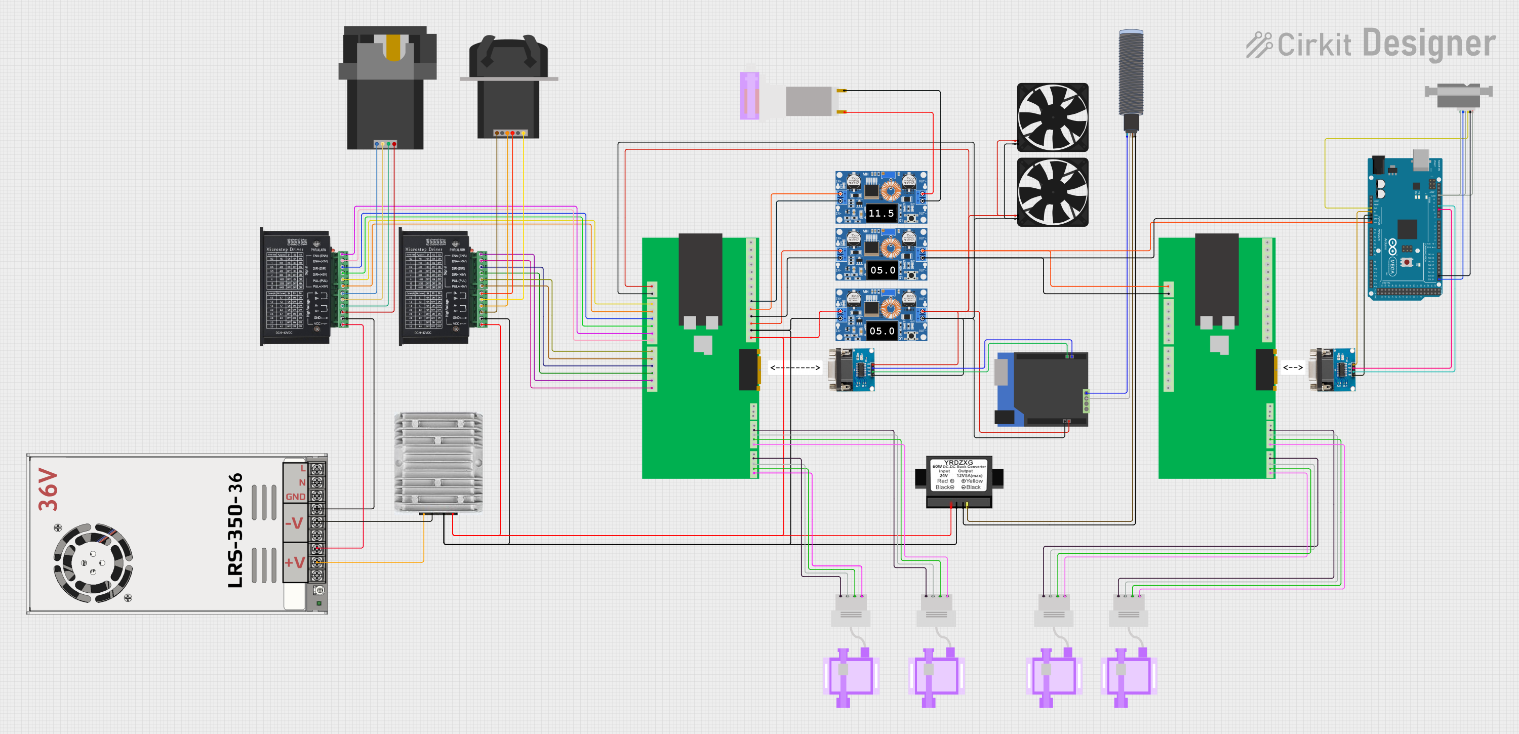
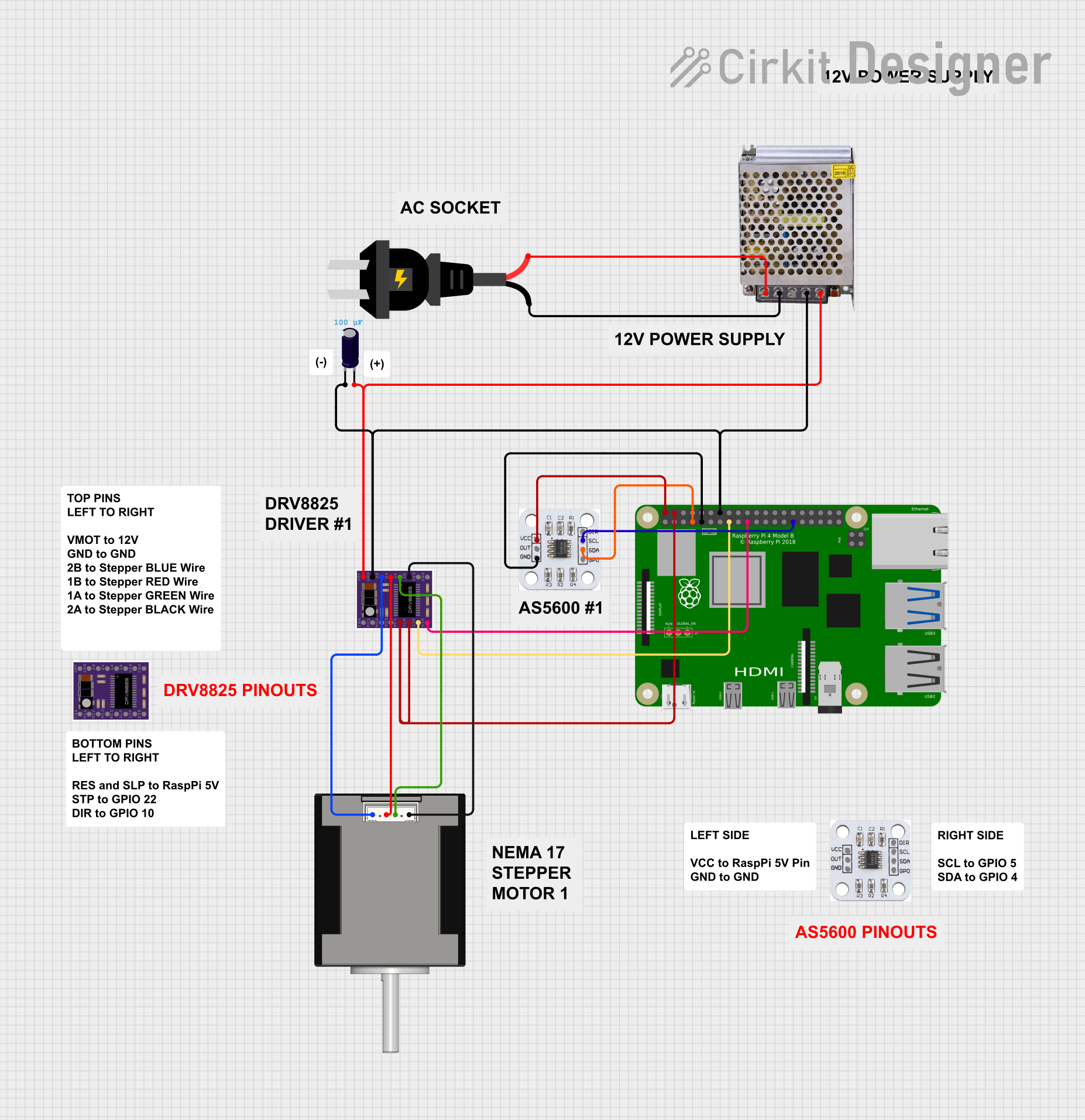
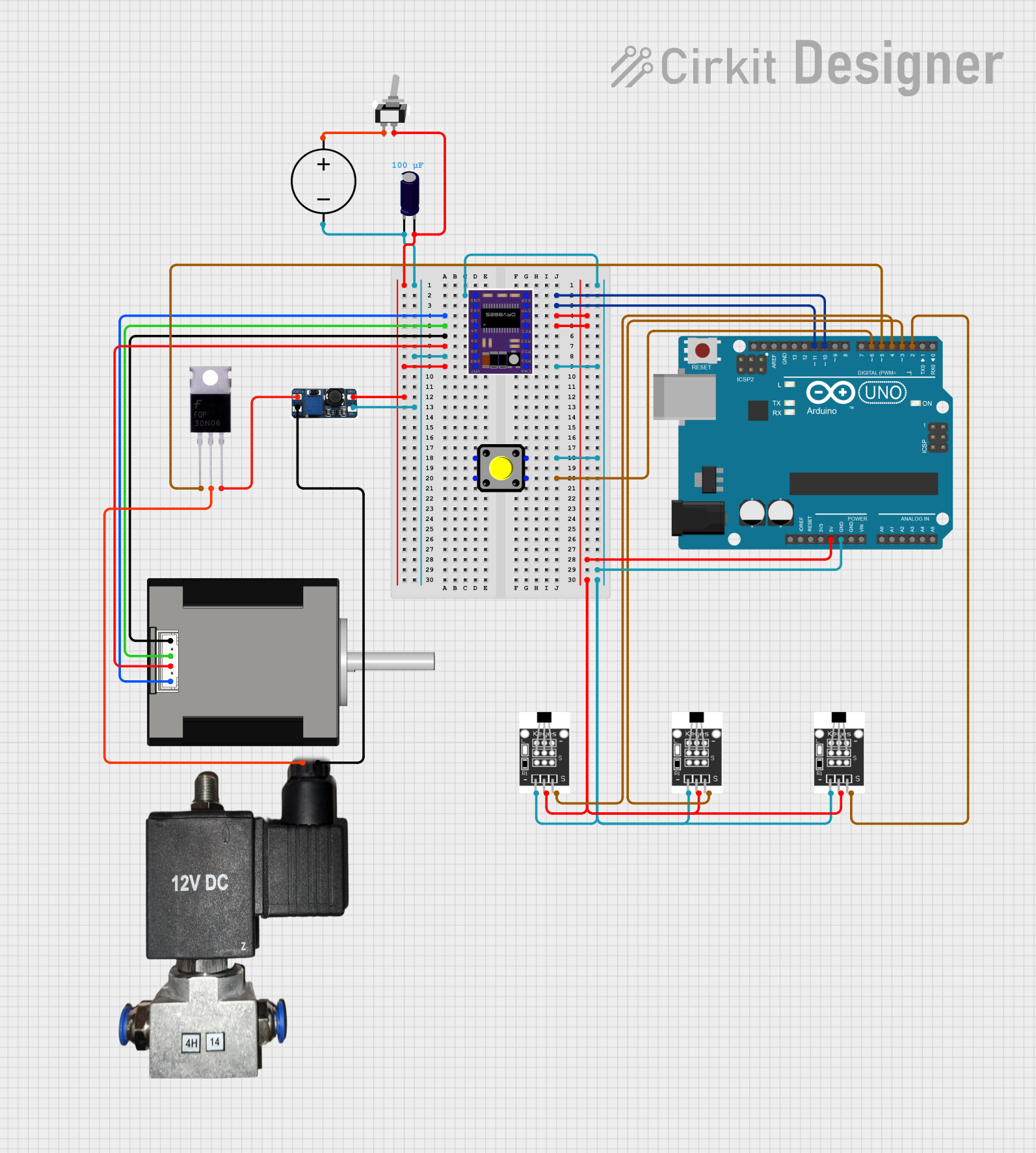

Explore Projects Built with PF25-48 Step Motor
Technical Specifications
Key Technical Details
| Parameter | Value |
|---|---|
| Manufacturer | NPM |
| Part ID | PF25-48 |
| Motor Type | Stepper Motor |
| Step Angle | 1.8° |
| Voltage Rating | 12V |
| Current Rating | 1.2A/phase |
| Holding Torque | 0.48 Nm |
| Number of Phases | 2 |
| Resistance/Phase | 10 Ohms |
| Inductance/Phase | 25 mH |
| Shaft Diameter | 5 mm |
| Motor Length | 48 mm |
| Weight | 280 g |
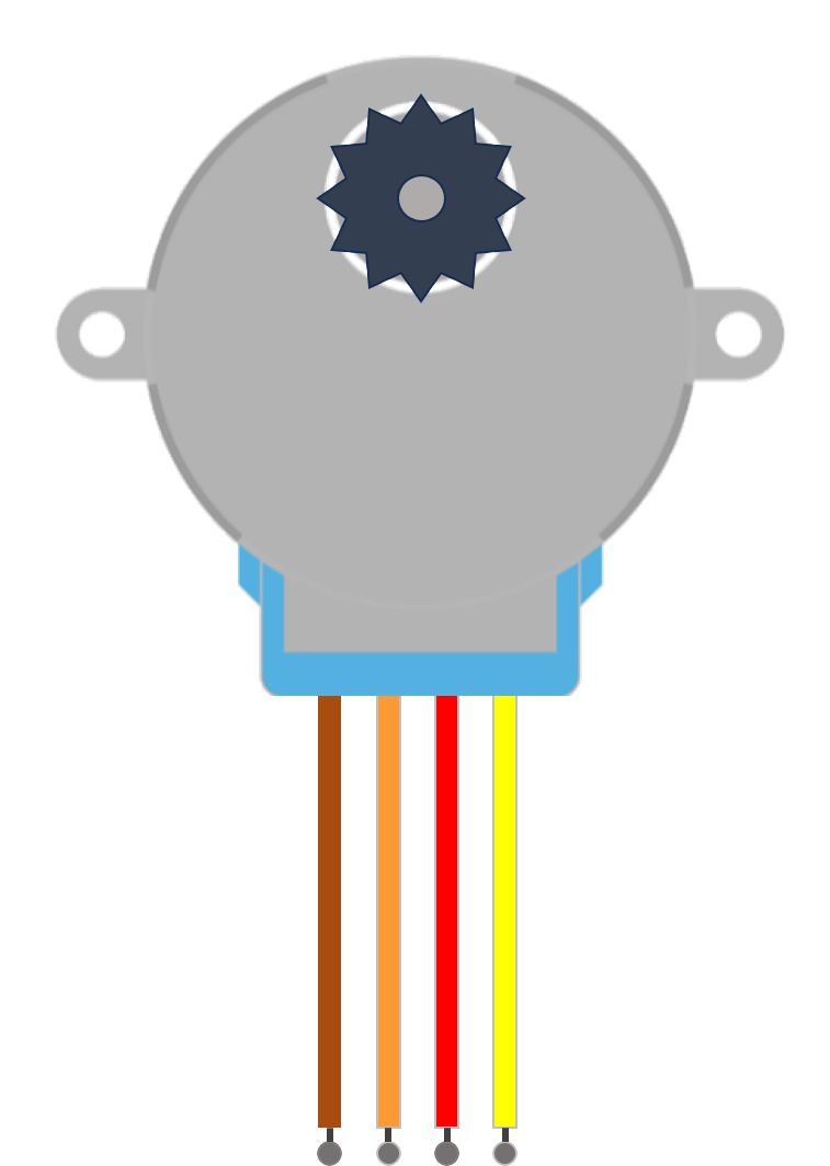
Pin Configuration and Descriptions
| Pin Number | Wire Color | Description |
|---|---|---|
| 1 | Red | Phase A |
| 2 | Blue | Phase A' |
| 3 | Green | Phase B |
| 4 | Black | Phase B' |
Usage Instructions
How to Use the PF25-48 Step Motor in a Circuit
To use the PF25-48 Step Motor in a circuit, you will need a stepper motor driver that can handle the motor's voltage and current ratings. The following steps outline the basic procedure for connecting and using the motor with an Arduino UNO:
Connect the Motor to the Driver:
- Connect the Red wire (Phase A) to the A+ terminal of the driver.
- Connect the Blue wire (Phase A') to the A- terminal of the driver.
- Connect the Green wire (Phase B) to the B+ terminal of the driver.
- Connect the Black wire (Phase B') to the B- terminal of the driver.
Connect the Driver to the Arduino:
- Connect the step, direction, and enable pins of the driver to the corresponding digital pins on the Arduino.
- Connect the ground (GND) of the driver to the GND of the Arduino.
- Connect the power supply to the driver, ensuring it matches the motor's voltage rating.
Upload the Code:
- Use the following example code to control the stepper motor with the Arduino:
#include <Stepper.h>

// Define the number of steps per revolution for your motor
const int stepsPerRevolution = 200;

// Initialize the stepper library on pins 8 through 11
Stepper myStepper(stepsPerRevolution, 8, 9, 10, 11);

void setup() {
  // Set the speed of the motor to 60 RPM
  myStepper.setSpeed(60);
  // Initialize the serial communication
  Serial.begin(9600);
}

void loop() {
  // Step one revolution in one direction
  Serial.println("Clockwise");
  myStepper.step(stepsPerRevolution);
  delay(1000);

  // Step one revolution in the other direction
  Serial.println("Counterclockwise");
  myStepper.step(-stepsPerRevolution);
  delay(1000);
}
Important Considerations and Best Practices
- Power Supply: Ensure that the power supply matches the motor's voltage rating (12V) and can provide sufficient current (1.2A/phase).
- Heat Dissipation: Stepper motors can generate heat during operation. Ensure proper ventilation or heat sinking to prevent overheating.
- Microstepping: If your driver supports microstepping, use it to achieve smoother motion and higher resolution.
- Current Limiting: Set the current limit on your driver to match the motor's current rating to prevent damage.
Troubleshooting and FAQs
Common Issues and Solutions
Motor Not Moving:
- Check Connections: Ensure all wires are connected correctly and securely.
- Power Supply: Verify that the power supply is providing the correct voltage and current.
- Code: Ensure the code is correctly uploaded to the Arduino and the pins are correctly defined.
Motor Vibrates but Doesn't Rotate:
- Phase Connections: Double-check the phase connections. Incorrect wiring can cause the motor to vibrate without rotating.
- Current Setting: Ensure the current limit on the driver is set correctly.
Motor Overheating:
- Current Limit: Reduce the current limit on the driver.
- Ventilation: Improve ventilation or add a heat sink to the motor.
FAQs
Q: Can I use a different voltage power supply? A: It is recommended to use a 12V power supply as specified. Using a different voltage may affect performance and could damage the motor.
Q: How do I increase the speed of the motor?
A: You can increase the speed by adjusting the RPM in the setSpeed() function in the code. However, ensure that the motor can handle the increased speed without losing steps.
Q: Can I use this motor with other microcontrollers? A: Yes, the PF25-48 Step Motor can be used with other microcontrollers, provided you have a compatible stepper motor driver and adjust the code accordingly.
This documentation provides a comprehensive guide to using the PF25-48 Step Motor. Whether you are a beginner or an experienced user, following these instructions and best practices will help you achieve precise and reliable performance in your projects.