How to Use Microphone Module: Examples, Pinouts, and Specs

Introduction
The SmartElex I2S MEMS Microphone Module is a compact and efficient device designed to convert sound waves into electrical signals. This module utilizes MEMS (Micro-Electro-Mechanical Systems) technology and supports the I2S (Inter-IC Sound) protocol for digital audio data transmission. It is ideal for applications requiring high-quality audio input, such as voice recognition systems, audio recording devices, and communication systems.
Explore Projects Built with Microphone Module
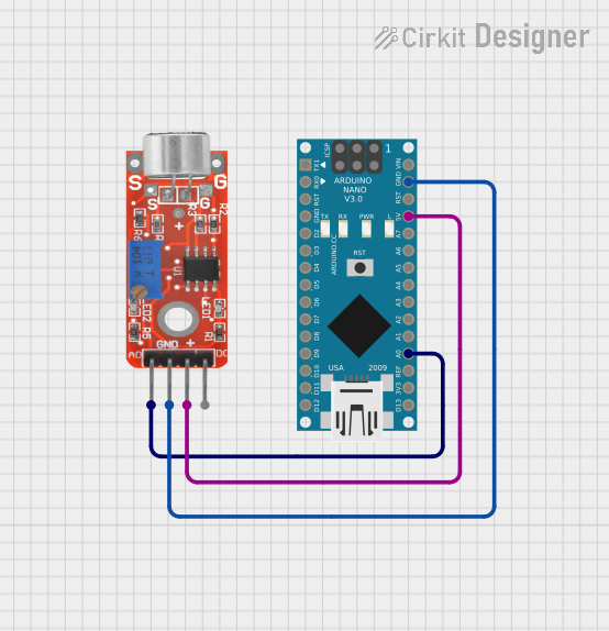
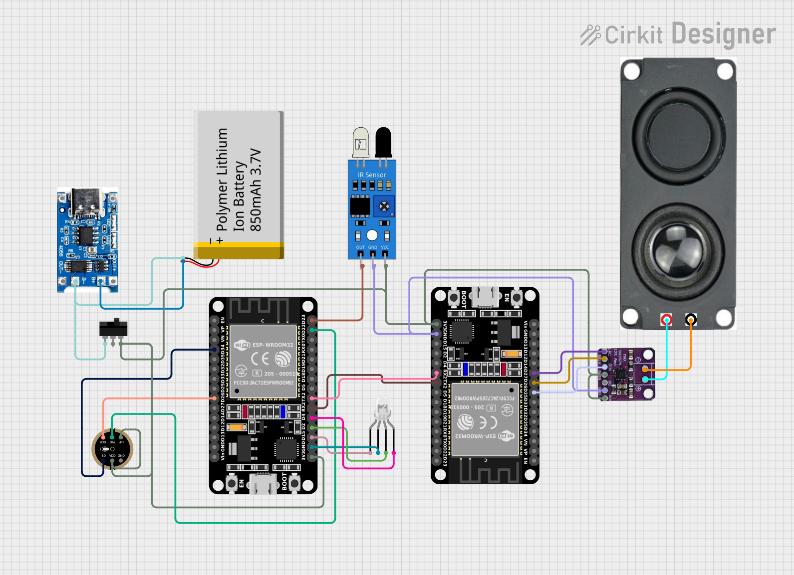
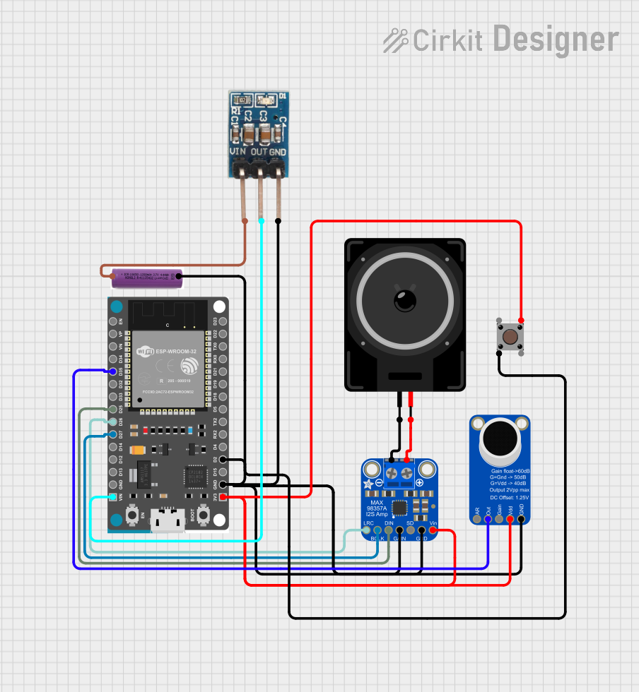
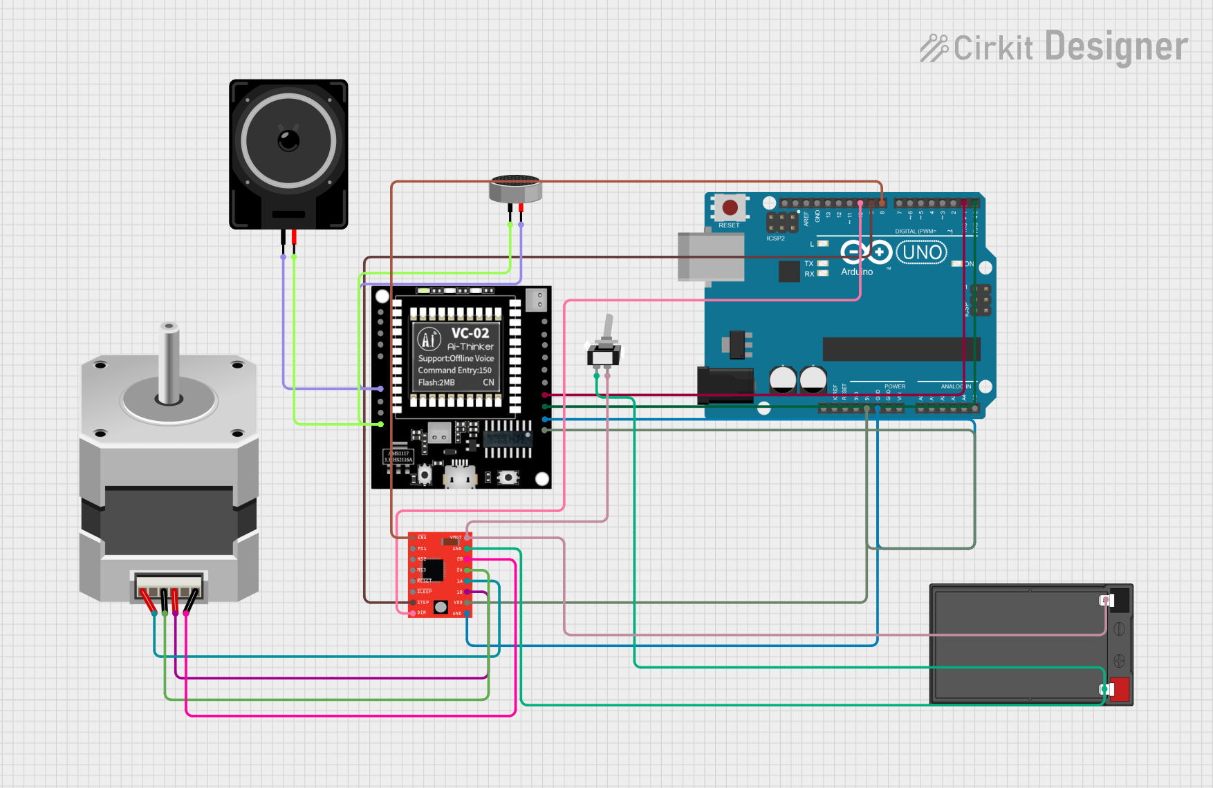
Explore Projects Built with Microphone Module
Common Applications
- Voice recognition systems (e.g., smart assistants)
- Audio recording and streaming
- IoT devices with sound input capabilities
- Communication systems (e.g., teleconferencing)
- Environmental sound monitoring
Technical Specifications
The following table outlines the key technical details of the SmartElex I2S MEMS Microphone Module:
| Parameter | Value |
|---|---|
| Manufacturer | SmartElex |
| Part ID | I2S MEMS |
| Operating Voltage | 1.8V to 3.6V |
| Current Consumption | < 1 mA |
| Output Format | I2S (Inter-IC Sound) |
| Frequency Response | 50 Hz to 20 kHz |
| Signal-to-Noise Ratio | 64 dB |
| Sensitivity | -26 dBFS ±3 dB |
| Dimensions | 15 mm x 10 mm x 2 mm |
| Operating Temperature | -40°C to +85°C |
Pin Configuration
The SmartElex I2S MEMS Microphone Module has the following pinout:
| Pin Name | Description |
|---|---|
| VDD | Power supply input (1.8V to 3.6V) |
| GND | Ground connection |
| WS | Word Select (Left/Right channel selection) |
| SCK | Serial Clock (I2S clock input) |
| SD | Serial Data (I2S audio data output) |
Usage Instructions
How to Use the Microphone Module in a Circuit
- Power Supply: Connect the VDD pin to a regulated power source (1.8V to 3.6V) and the GND pin to the ground.
- I2S Interface: Connect the WS, SCK, and SD pins to the corresponding I2S pins on your microcontroller or audio processor.
- WS: Used to select the left or right audio channel.
- SCK: Provides the clock signal for data synchronization.
- SD: Outputs the digital audio data.
- Configuration: Ensure your microcontroller or processor is configured to read I2S data at the appropriate clock rate and channel settings.
Important Considerations and Best Practices
- Power Supply: Use a stable and noise-free power source to avoid interference in audio signals.
- Clock Signal: Ensure the SCK signal is accurate and matches the required frequency for proper data synchronization.
- Placement: Place the microphone module away from high-frequency noise sources to maintain audio quality.
- Decoupling Capacitor: Add a decoupling capacitor (e.g., 0.1 µF) near the VDD pin to filter out power supply noise.
Example: Connecting to an Arduino UNO
The Arduino UNO does not natively support I2S, but you can use an external I2S interface module or a microcontroller like the ESP32, which has built-in I2S support. Below is an example code snippet for using the I2S MEMS Microphone Module with an ESP32:
#include <driver/i2s.h>

// I2S configuration
#define I2S_NUM         I2S_NUM_0  // I2S port number
#define I2S_WS_PIN      25         // Word Select pin
#define I2S_SCK_PIN     26         // Serial Clock pin
#define I2S_SD_PIN      22         // Serial Data pin

void setup() {
  // Configure I2S
  i2s_config_t i2s_config = {
    .mode = (i2s_mode_t)(I2S_MODE_MASTER | I2S_MODE_RX), // Master mode, receive
    .sample_rate = 16000,                               // Sampling rate
    .bits_per_sample = I2S_BITS_PER_SAMPLE_16BIT,       // 16-bit audio
    .channel_format = I2S_CHANNEL_FMT_ONLY_LEFT,        // Left channel only
    .communication_format = I2S_COMM_FORMAT_I2S,       // I2S format
    .intr_alloc_flags = ESP_INTR_FLAG_LEVEL1,           // Interrupt level
    .dma_buf_count = 8,                                 // Number of DMA buffers
    .dma_buf_len = 64                                   // Buffer length
  };

  // Configure I2S pins
  i2s_pin_config_t pin_config = {
    .bck_io_num = I2S_SCK_PIN,  // Serial Clock
    .ws_io_num = I2S_WS_PIN,    // Word Select
    .data_out_num = I2S_PIN_NO_CHANGE, // Not used
    .data_in_num = I2S_SD_PIN   // Serial Data
  };

  // Install and start I2S driver
  i2s_driver_install(I2S_NUM, &i2s_config, 0, NULL);
  i2s_set_pin(I2S_NUM, &pin_config);
}

void loop() {
  // Buffer to store audio data
  int16_t audio_buffer[128];
  size_t bytes_read;

  // Read audio data from I2S
  i2s_read(I2S_NUM, audio_buffer, sizeof(audio_buffer), &bytes_read, portMAX_DELAY);

  // Process audio data (e.g., send to a server or analyze)
}
Troubleshooting and FAQs
Common Issues
No Audio Output:
- Ensure the power supply is within the specified range (1.8V to 3.6V).
- Verify the I2S clock signal (SCK) is correctly configured.
- Check the connections for WS, SCK, and SD pins.
Distorted Audio:
- Ensure the microphone is not placed near high-frequency noise sources.
- Verify the sampling rate and bit depth match the module's specifications.
Low Sensitivity:
- Check if the microphone is oriented correctly to capture sound.
- Ensure there are no obstructions blocking the microphone's sound input.
FAQs
Q: Can this module be used with a Raspberry Pi?
A: Yes, the I2S MEMS Microphone Module can be connected to a Raspberry Pi using its I2S interface. Ensure the Raspberry Pi is configured to read I2S data.
Q: What is the maximum sampling rate supported?
A: The module supports sampling rates up to 48 kHz, depending on the configuration of the I2S interface.
Q: Can I use this module for stereo audio?
A: Yes, by using two modules and configuring the WS pin appropriately, you can capture stereo audio.
Q: Is this module suitable for outdoor use?
A: The module operates in a wide temperature range (-40°C to +85°C), but it should be protected from moisture and dust for reliable operation.