How to Use Light Sensor TSL25911: Examples, Pinouts, and Specs
Introduction
The TSL25911 by Waveshare (Manufacturer Part ID: 17146) is a high-performance light-to-digital converter designed for precise ambient light sensing. It features a wide dynamic range, enabling it to measure light levels from extremely dark to very bright environments. This makes it an excellent choice for applications requiring adaptive brightness control, such as smartphones, tablets, and other consumer electronics.
Explore Projects Built with Light Sensor TSL25911
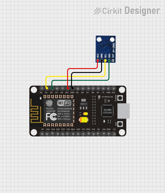
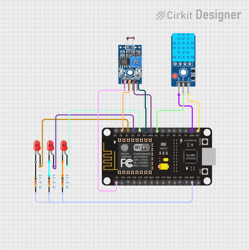

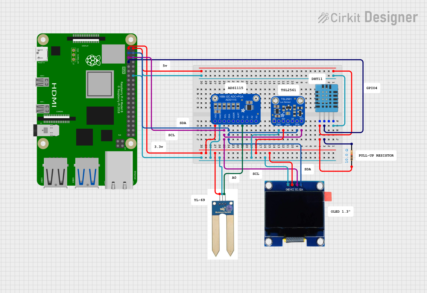
Explore Projects Built with Light Sensor TSL25911
Common Applications and Use Cases
- Adaptive brightness control in smartphones, tablets, and laptops
- Ambient light sensing for smart home devices
- Display backlight adjustment
- Industrial and medical light measurement
- Energy-efficient lighting systems
Technical Specifications
The TSL25911 is a highly sensitive and versatile light sensor. Below are its key technical details:
| Parameter | Value |
|---|---|
| Operating Voltage | 2.0V to 3.6V |
| Communication Interface | I²C (up to 400 kHz) |
| Spectral Response | 400 nm to 800 nm |
| Dynamic Range | 600M:1 |
| Lux Range | 0.0001 lux to 88,000 lux |
| Operating Temperature | -30°C to +85°C |
| Power Consumption | 2.5 µA (low-power mode) |
| Package Type | 2 mm × 2 mm × 0.6 mm (FN package) |
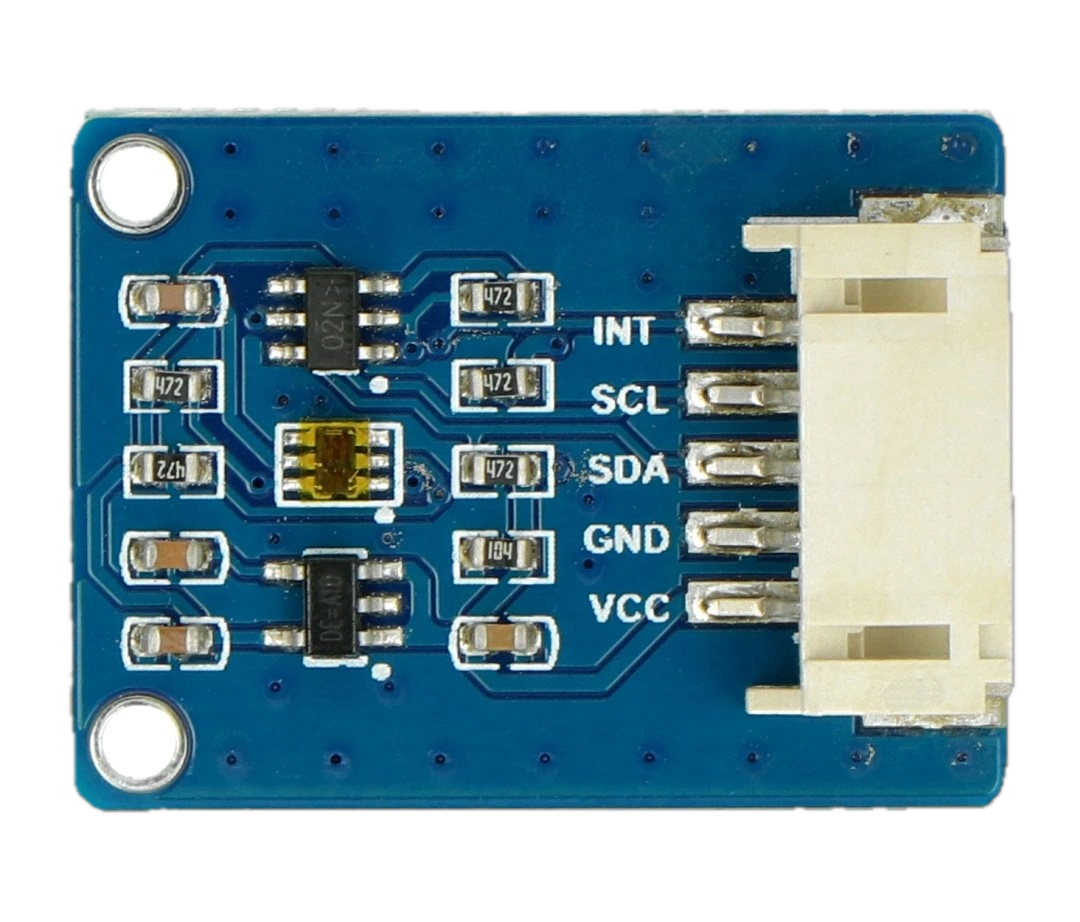
Pin Configuration and Descriptions
The TSL25911 has six pins, as described in the table below:
| Pin Name | Pin Number | Description |
|---|---|---|
| GND | 1 | Ground pin |
| VDD | 2 | Power supply pin (2.0V to 3.6V) |
| SDA | 3 | I²C data line |
| SCL | 4 | I²C clock line |
| INT | 5 | Interrupt output (active low) |
| ADDR | 6 | I²C address selection (connect to GND or VDD) |
Usage Instructions
The TSL25911 is straightforward to use in a circuit, thanks to its I²C interface. Below are the steps and considerations for integrating it into your project:
Circuit Connection
- Power Supply: Connect the VDD pin to a 3.3V power source and the GND pin to ground.
- I²C Communication: Connect the SDA and SCL pins to the corresponding I²C pins on your microcontroller (e.g., Arduino UNO: A4 for SDA, A5 for SCL).
- Interrupt Pin (Optional): The INT pin can be used to signal when a light measurement is ready. If unused, leave it unconnected.
- I²C Address Selection: Use the ADDR pin to set the I²C address:
- Connect to GND for address
0x29. - Connect to VDD for address
0x49.
- Connect to GND for address
Arduino UNO Example Code
Below is an example of how to use the TSL25911 with an Arduino UNO. This code reads the ambient light level and prints it to the Serial Monitor.
#include <Wire.h>
#include <Adafruit_Sensor.h>
#include <Adafruit_TSL2591.h>

// Create an instance of the TSL2591 sensor
Adafruit_TSL2591 tsl = Adafruit_TSL2591(2591);

void configureSensor() {
  // Set gain and integration time for the sensor
  tsl.setGain(TSL2591_GAIN_MED); // Options: LOW, MED, HIGH, MAX
  tsl.setTiming(TSL2591_INTEGRATIONTIME_100MS); // Options: 100MS, 200MS, etc.

  // Print configuration details
  Serial.println(F("TSL25911 configured with medium gain and 100ms integration time."));
}

void setup() {
  Serial.begin(9600); // Initialize Serial Monitor
  if (!tsl.begin()) {
    Serial.println(F("Failed to find TSL25911 sensor! Check connections."));
    while (1); // Halt execution if sensor is not found
  }
  Serial.println(F("TSL25911 sensor found!"));
  configureSensor();
}

void loop() {
  // Get the full spectrum (visible + IR) and infrared light levels
  uint16_t fullSpectrum = tsl.getFullLuminosity() & 0xFFFF;
  uint16_t infrared = tsl.getFullLuminosity() >> 16;

  // Calculate visible light by subtracting infrared from full spectrum
  uint16_t visible = fullSpectrum - infrared;

  // Print light levels to Serial Monitor
  Serial.print(F("Full Spectrum: ")); Serial.print(fullSpectrum);
  Serial.print(F(" Infrared: ")); Serial.print(infrared);
  Serial.print(F(" Visible: ")); Serial.println(visible);

  delay(1000); // Wait 1 second before next reading
}
Important Considerations and Best Practices
- Power Supply: Ensure a stable 3.3V power source to avoid measurement errors.
- I²C Pull-Up Resistors: Use 4.7kΩ pull-up resistors on the SDA and SCL lines if your microcontroller does not have internal pull-ups.
- Gain and Integration Time: Adjust the sensor's gain and integration time based on your application's lighting conditions to optimize accuracy.
- Interrupt Pin: Use the INT pin for efficient event-driven programming, especially in low-power applications.
Troubleshooting and FAQs
Common Issues and Solutions
Sensor Not Detected
- Cause: Incorrect I²C address or wiring.
- Solution: Verify the ADDR pin connection and ensure SDA/SCL are correctly connected.
Inaccurate Light Measurements
- Cause: Incorrect gain or integration time settings.
- Solution: Adjust the gain and integration time to match the lighting conditions.
No Output on Serial Monitor
- Cause: Serial communication not initialized or incorrect baud rate.
- Solution: Ensure
Serial.begin(9600)matches the Serial Monitor's baud rate.
High Power Consumption
- Cause: Sensor not in low-power mode.
- Solution: Use the sensor's low-power mode when continuous measurements are not required.
FAQs
Q: Can the TSL25911 measure UV light?
A: No, the TSL25911 is designed to measure visible and infrared light, with a spectral response range of 400 nm to 800 nm.
Q: What is the maximum I²C clock speed supported?
A: The TSL25911 supports I²C communication at speeds up to 400 kHz.
Q: Can I use the TSL25911 with a 5V microcontroller?
A: Yes, but you must use a level shifter to safely interface the 3.3V sensor with the 5V logic of the microcontroller.
Q: How do I calculate lux from the sensor readings?
A: Use the Adafruit TSL2591 library, which provides built-in functions to calculate lux based on the sensor's raw data.
By following this documentation, you can effectively integrate the TSL25911 into your projects and achieve precise ambient light sensing.