How to Use toggle swich: Examples, Pinouts, and Specs

Introduction
A toggle switch is a mechanical switch that is operated by a lever or handle, allowing the user to turn a circuit on or off. It is one of the most commonly used switches in electronic circuits due to its simplicity, durability, and reliability. Toggle switches are available in various configurations, such as single-pole single-throw (SPST), single-pole double-throw (SPDT), and double-pole double-throw (DPDT), making them versatile for a wide range of applications.
Explore Projects Built with toggle swich

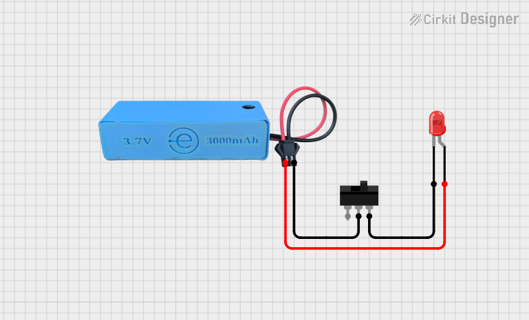
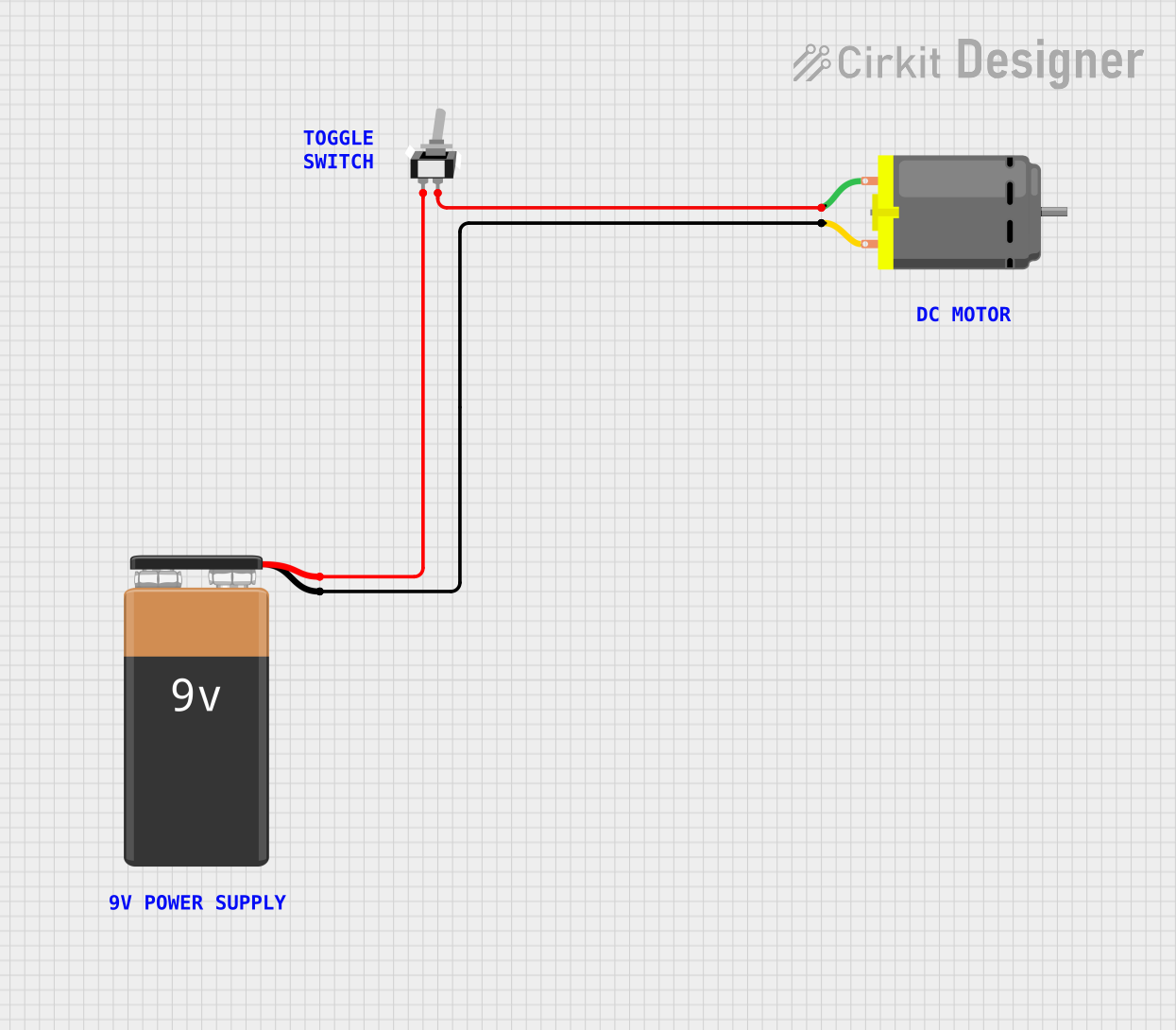
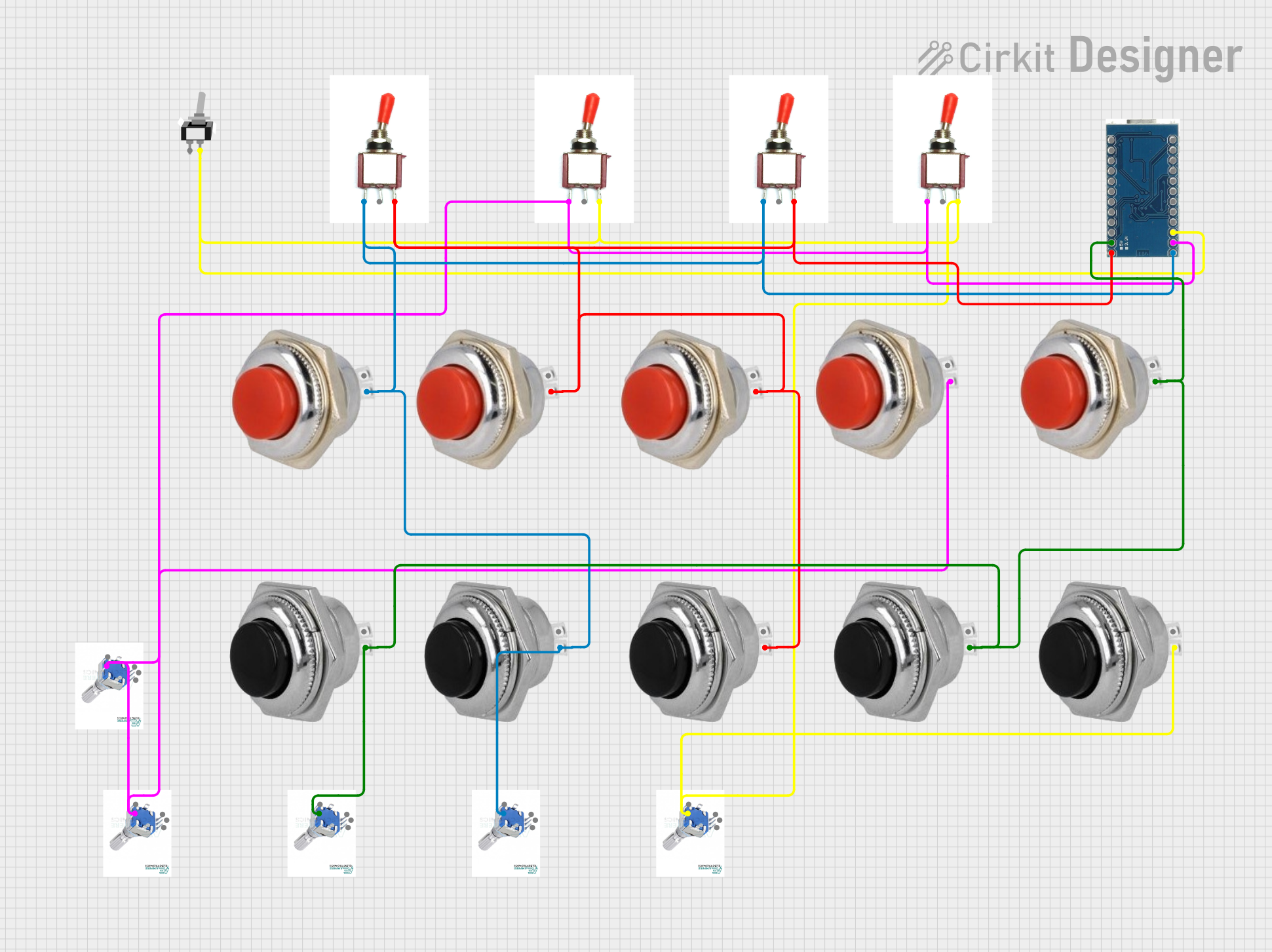
Explore Projects Built with toggle swich
Common Applications and Use Cases
- Power control in electronic devices
- Light switches in homes and vehicles
- Mode selection in industrial equipment
- Audio and video equipment control
- Robotics and DIY electronics projects
Technical Specifications
Below are the general technical specifications for a standard toggle switch. Note that specific values may vary depending on the manufacturer and model.
| Parameter | Description |
|---|---|
| Voltage Rating | Typically 12V to 250V (AC or DC, depending on the switch type) |
| Current Rating | Commonly 2A to 15A |
| Contact Resistance | ≤ 50 mΩ |
| Insulation Resistance | ≥ 100 MΩ |
| Operating Temperature | -20°C to 85°C |
| Mechanical Life | 50,000 to 100,000 cycles |
Pin Configuration and Descriptions
The pin configuration of a toggle switch depends on its type. Below are the configurations for the most common types:
Single-Pole Single-Throw (SPST)
| Pin | Description |
|---|---|
| Pin 1 | Input terminal (connect to power) |
| Pin 2 | Output terminal (connect to load) |
Single-Pole Double-Throw (SPDT)
| Pin | Description |
|---|---|
| Pin 1 | Common terminal |
| Pin 2 | Normally Closed (NC) terminal |
| Pin 3 | Normally Open (NO) terminal |
Double-Pole Double-Throw (DPDT)
| Pin | Description |
|---|---|
| Pin 1 | Common terminal for pole 1 |
| Pin 2 | NC terminal for pole 1 |
| Pin 3 | NO terminal for pole 1 |
| Pin 4 | Common terminal for pole 2 |
| Pin 5 | NC terminal for pole 2 |
| Pin 6 | NO terminal for pole 2 |
Usage Instructions
How to Use the Component in a Circuit
- Identify the Type of Toggle Switch: Determine whether the switch is SPST, SPDT, or DPDT based on your circuit requirements.
- Connect the Terminals:
- For SPST: Connect one terminal to the power source and the other to the load.
- For SPDT: Connect the common terminal to the power source, and use the NC and NO terminals to control two different outputs.
- For DPDT: Use the two poles to control two separate circuits simultaneously.
- Secure the Switch: Mount the toggle switch in a suitable enclosure or panel to ensure stability and safety.
- Test the Circuit: Verify the connections and test the switch operation to ensure proper functionality.
Important Considerations and Best Practices
- Voltage and Current Ratings: Always ensure the toggle switch can handle the voltage and current of your circuit to avoid damage or failure.
- Debouncing: Mechanical switches may cause bouncing, which can lead to erratic signals in digital circuits. Use a capacitor or software debouncing techniques to mitigate this issue.
- Safety: When working with high voltages, ensure proper insulation and grounding to prevent electrical hazards.
- Durability: Choose a switch with a mechanical life rating suitable for the expected usage frequency.
Example: Connecting a Toggle Switch to an Arduino UNO
Below is an example of using an SPST toggle switch to control an LED with an Arduino UNO:
// Define pin numbers
const int toggleSwitchPin = 2; // Pin connected to the toggle switch
const int ledPin = 13;         // Pin connected to the LED

void setup() {
  pinMode(toggleSwitchPin, INPUT_PULLUP); // Set toggle switch pin as input with pull-up
  pinMode(ledPin, OUTPUT);               // Set LED pin as output
}

void loop() {
  int switchState = digitalRead(toggleSwitchPin); // Read the state of the toggle switch

  if (switchState == LOW) { // If the switch is ON (connected to GND)
    digitalWrite(ledPin, HIGH); // Turn the LED ON
  } else { // If the switch is OFF
    digitalWrite(ledPin, LOW);  // Turn the LED OFF
  }
}
Note: The
INPUT_PULLUPmode is used to simplify the circuit by enabling the internal pull-up resistor of the Arduino.
Troubleshooting and FAQs
Common Issues Users Might Face
Switch Not Working:
- Cause: Loose or incorrect wiring.
- Solution: Double-check the connections and ensure the terminals are properly secured.
Switch Feels Stiff or Loose:
- Cause: Mechanical wear or damage.
- Solution: Replace the switch if it is physically damaged.
LED or Load Not Responding:
- Cause: Incorrect pin configuration or insufficient power supply.
- Solution: Verify the pin connections and ensure the power supply meets the circuit requirements.
Erratic Behavior in Digital Circuits:
- Cause: Switch bouncing.
- Solution: Add a capacitor across the switch terminals or implement software debouncing.
FAQs
Q: Can I use a toggle switch to control AC devices?
A: Yes, but ensure the switch is rated for the voltage and current of the AC device. Use proper insulation and safety precautions.
Q: How do I know if my toggle switch is SPST, SPDT, or DPDT?
A: Check the number of terminals and the switch's datasheet. SPST has 2 terminals, SPDT has 3, and DPDT has 6.
Q: Can I use a toggle switch with a microcontroller?
A: Yes, toggle switches can be used as input devices for microcontrollers. Use pull-up or pull-down resistors to ensure stable signals.
Q: What is the difference between NC and NO terminals?
A: NC (Normally Closed) means the circuit is closed when the switch is in its default position, while NO (Normally Open) means the circuit is open in the default position.