How to Use sensor proximity infrared: Examples, Pinouts, and Specs
Introduction
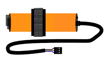
The E18-D80NK Photoelectric Switch, manufactured by LEFIRCKO, is an infrared proximity sensor designed to detect the presence of nearby objects using infrared light. This sensor is widely used in automation, robotics, and safety applications due to its reliability, ease of use, and adjustable detection range. It is particularly suitable for object detection, obstacle avoidance, and non-contact sensing in industrial and consumer electronics.
Explore Projects Built with sensor proximity infrared


Explore Projects Built with sensor proximity infrared
Common Applications
- Object detection in conveyor belt systems
- Obstacle avoidance in robotics
- Automatic door systems
- Safety barriers and intrusion detection
- Liquid level detection in transparent containers
Technical Specifications
The following table outlines the key technical details of the E18-D80NK Photoelectric Switch:
| Parameter | Value |
|---|---|
| Manufacturer | LEFIRCKO |
| Part ID | E18-D80NK |
| Detection Range | 3 cm to 80 cm (adjustable) |
| Operating Voltage | 5V to 24V DC |
| Output Type | Digital (High/Low) |
| Output Current | ≤ 100 mA |
| Response Time | ≤ 2 ms |
| Wavelength | 940 nm (infrared light) |
| Operating Temperature | -25°C to 55°C |
| Dimensions | 18 mm (diameter) x 45 mm (length) |
| Cable Length | 45 cm |
Pin Configuration
The E18-D80NK has a 3-wire interface for easy integration into circuits. The pinout is as follows:
| Wire Color | Function | Description |
|---|---|---|
| Brown | VCC | Connect to the positive supply voltage (5V to 24V). |
| Blue | GND | Connect to ground. |
| Black | Signal Output | Outputs a digital signal (High/Low) based on object detection. |
Usage Instructions
How to Use the E18-D80NK in a Circuit
- Power the Sensor: Connect the brown wire to the positive voltage supply (5V to 24V DC) and the blue wire to ground.
- Connect the Output: Connect the black wire to a digital input pin of your microcontroller or to a relay module for controlling external devices.
- Adjust the Detection Range: Use the potentiometer on the sensor to set the desired detection range (3 cm to 80 cm). Turn clockwise to increase the range and counterclockwise to decrease it.
- Test the Sensor: Place an object within the detection range and observe the output signal. The black wire will output a HIGH signal when an object is detected and a LOW signal otherwise.
Important Considerations
- Power Supply: Ensure the power supply voltage is within the specified range (5V to 24V DC) to avoid damaging the sensor.
- Ambient Light: The sensor may be affected by strong ambient light or reflective surfaces. Test and adjust the sensor in the intended environment.
- Mounting: Secure the sensor firmly to prevent misalignment or vibration, which could affect detection accuracy.
- Wiring Length: If extending the wires, use shielded cables to minimize noise interference.
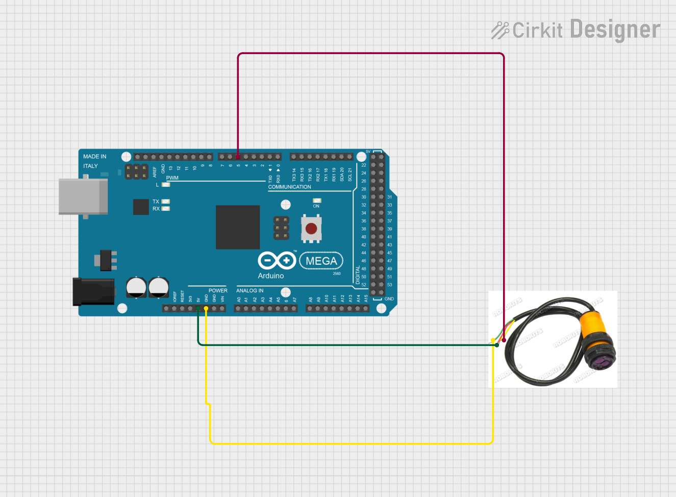
Example: Connecting to an Arduino UNO
Below is an example of how to connect and use the E18-D80NK with an Arduino UNO:
Circuit Connections
- Brown wire: Connect to the Arduino's 5V pin.
- Blue wire: Connect to the Arduino's GND pin.
- Black wire: Connect to a digital input pin (e.g., D2).
Arduino Code
// E18-D80NK Photoelectric Switch Example
// This code reads the sensor's output and prints the detection status to the Serial Monitor.

const int sensorPin = 2; // Digital pin connected to the sensor's black wire
int sensorState = 0;     // Variable to store the sensor's state

void setup() {
  pinMode(sensorPin, INPUT); // Set the sensor pin as an input
  Serial.begin(9600);        // Initialize serial communication at 9600 baud
}

void loop() {
  sensorState = digitalRead(sensorPin); // Read the sensor's output

  if (sensorState == HIGH) {
    // Object detected
    Serial.println("Object detected!");
  } else {
    // No object detected
    Serial.println("No object detected.");
  }

  delay(100); // Small delay to avoid flooding the Serial Monitor
}
Troubleshooting and FAQs
Common Issues and Solutions
Sensor Not Detecting Objects
- Cause: Incorrect wiring or insufficient power supply.
- Solution: Double-check the wiring and ensure the power supply voltage is within the specified range (5V to 24V DC).
False Detections
- Cause: Strong ambient light or reflective surfaces.
- Solution: Adjust the sensor's position or shield it from direct light sources. Use the potentiometer to fine-tune the detection range.
Output Signal Not Changing
- Cause: Faulty sensor or incorrect connection to the microcontroller.
- Solution: Test the sensor with a multimeter to verify the output signal. Ensure the black wire is connected to the correct digital input pin.
Interference in Long Cables
- Cause: Noise interference in extended wiring.
- Solution: Use shielded cables and keep the wiring as short as possible.
FAQs
Q1: Can the E18-D80NK detect transparent objects?
A1: Yes, the sensor can detect transparent objects, but its performance may vary depending on the object's material and thickness. Adjust the detection range for optimal results.
Q2: Is the sensor waterproof?
A2: The E18-D80NK is not fully waterproof. It is recommended to use it in dry environments or protect it with a waterproof enclosure.
Q3: Can I use the sensor with a 3.3V microcontroller?
A3: The sensor requires a minimum operating voltage of 5V. However, the output signal can be interfaced with a 3.3V microcontroller using a voltage divider or level shifter.
Q4: How do I extend the detection range beyond 80 cm?
A4: The E18-D80NK is limited to a maximum range of 80 cm. For longer ranges, consider using a different sensor model designed for extended distances.
This concludes the documentation for the E18-D80NK Photoelectric Switch. For further assistance, refer to the manufacturer's datasheet or contact LEFIRCKO support.