How to Use Arduino: Examples, Pinouts, and Specs
Introduction
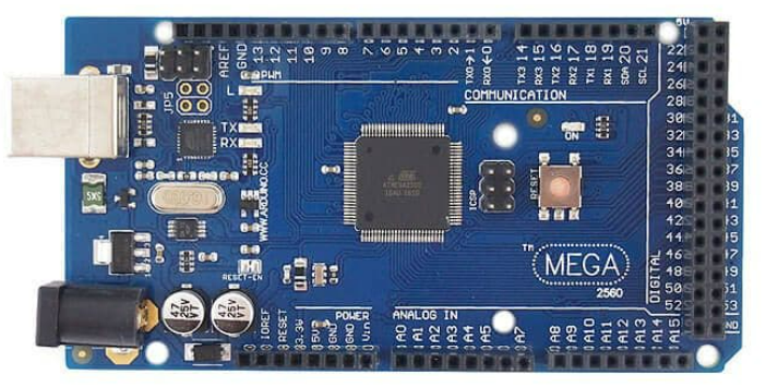
The Arduino Mega 2560 is a microcontroller board based on the ATmega2560. It is an integral part of the Arduino open-source electronics platform, which is known for its ease of use and extensive community support. The Mega 2560 is designed for projects that require more I/O lines, more sketch memory, and more RAM. With its 54 digital input/output pins, 16 analog inputs, and a larger space for your sketches, it is the recommended board for 3D printers and robotics projects.
Explore Projects Built with Arduino

Explore Projects Built with Arduino
Common Applications and Use Cases
- Robotics
- 3D printing
- Home automation
- Complex LED installations
- Prototyping IoT devices
Technical Specifications
Key Technical Details
- Microcontroller: ATmega2560
- Operating Voltage: 5V
- Input Voltage (recommended): 7-12V
- Input Voltage (limit): 6-20V
- Digital I/O Pins: 54 (of which 15 provide PWM output)
- Analog Input Pins: 16
- DC Current per I/O Pin: 20 mA
- DC Current for 3.3V Pin: 50 mA
- Flash Memory: 256 KB of which 8 KB used by bootloader
- SRAM: 8 KB
- EEPROM: 4 KB
- Clock Speed: 16 MHz
- LED_BUILTIN: Pin 13
Pin Configuration and Descriptions
| Pin Number | Function | Description |
|---|---|---|
| 1-54 | Digital I/O | Digital input/output pins (0-53) |
| 1-16 | PWM | PWM output available on pins (2-13, 44-46) |
| 17-32 | Analog Input | Analog input pins (A0-A15) |
| 33 | Reset | Resets the microcontroller |
| 34-37 | GND | Ground pins |
| 38-41 | 5V | 5V power pins |
| 42-43 | 3.3V | 3.3V power pins |
| 44 | Vin | Input voltage to the Arduino board |
| 45-46 | IOREF | Input/output reference voltage |
| 47-50 | Reserved | Reserved for future use |
| 51-54 | Communication | TX0/RX0, TX1/RX1, TX2/RX2, TX3/RX3 |
Usage Instructions
How to Use the Component in a Circuit
Powering the Board:
- Connect a 7-12V power supply to the Vin pin and GND, or use the DC power jack.
Connecting I/O Devices:
- Digital devices: Connect to digital pins 0-53.
- Analog devices: Connect to analog pins A0-A15.
- PWM devices: Connect to PWM-enabled digital pins 2-13, 44-46.
Programming the Board:
- Connect the board to a computer using a USB cable.
- Use the Arduino IDE to write and upload sketches to the board.
Important Considerations and Best Practices
- Do not exceed the recommended input voltage as it may damage the board.
- Ensure that the total current through all I/O pins does not exceed the limit.
- Use external power supplies when connecting power-hungry devices.
- Disconnect the power source when assembling or modifying circuits.
Troubleshooting and FAQs
Common Issues
Board not recognized by the computer:
- Check the USB cable and connections.
- Ensure the correct drivers are installed.
Sketch not uploading:
- Verify the correct board and port are selected in the Arduino IDE.
- Press the reset button on the board and try uploading again.
Insufficient power to external components:
- Use an external power supply for components that draw more current.
FAQs
Can I use the Arduino Mega 2560 at a voltage lower than 7V?
- It is not recommended as the board may not operate reliably.
How many devices can I connect to the digital pins?
- You can connect one device per pin, but ensure the total current does not exceed the limit.
What is the purpose of the IOREF pin?
- The IOREF pin provides the voltage reference with which the microcontroller operates.
Example Code for Arduino UNO
Here is a simple example of blinking an LED connected to pin 13 on the Arduino Mega 2560:
// Define the LED pin
const int ledPin = 13;

// The setup function runs once when you press reset or power the board
void setup() {
  // Initialize the digital pin as an output.
  pinMode(ledPin, OUTPUT);
}

// The loop function runs over and over again forever
void loop() {
  digitalWrite(ledPin, HIGH);   // Turn the LED on
  delay(1000);                  // Wait for a second
  digitalWrite(ledPin, LOW);    // Turn the LED off
  delay(1000);                  // Wait for a second
}
Remember to select "Arduino Mega or Mega 2560" as the board within the Arduino IDE before uploading the code.