How to Use Adafruit STMPE610 Breakout: Examples, Pinouts, and Specs
Introduction
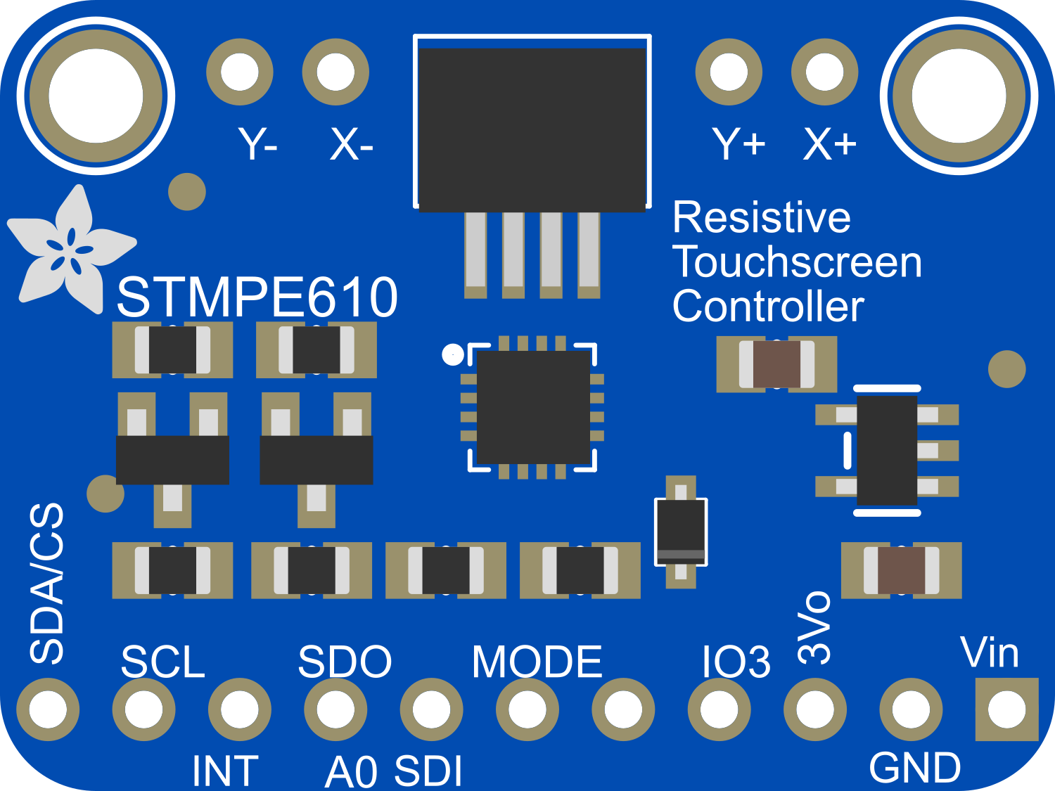
The Adafruit STMPE610 Breakout is a versatile and user-friendly interface for the STMPE610 resistive touch screen controller. This breakout board simplifies the process of integrating touch sensing capabilities into a wide array of projects, from interactive art installations to sophisticated control panels. The STMPE610 controller is capable of detecting touch inputs and translating them into digital signals that can be processed by microcontrollers such as the Arduino UNO.
Explore Projects Built with Adafruit STMPE610 Breakout

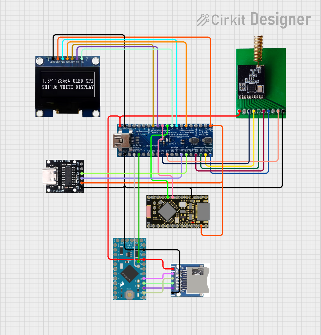
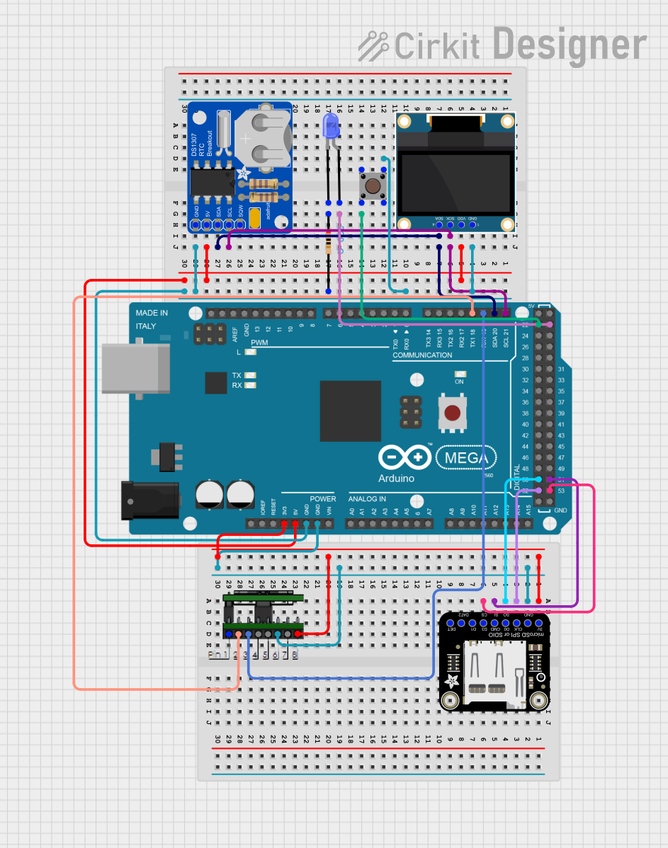

Explore Projects Built with Adafruit STMPE610 Breakout
Common Applications and Use Cases
- Touch-enabled user interfaces
- Interactive kiosks
- Home automation control panels
- DIY tablets and custom touchscreens
- Prototyping and educational projects
Technical Specifications
Key Technical Details
- Operating Voltage: 2.5V to 3.3V
- Current Consumption: Typical 3mA, Max 10mA
- Resolution: 12-bit, 4096 x 4096
- Interface: I2C (up to 400 KHz) and SPI (up to 1 MHz)
- Operating Temperature: -40°C to +85°C
Pin Configuration and Descriptions
| Pin Number | Pin Name | Description |
|---|---|---|
| 1 | VIN | Power supply (2.5V to 3.3V) |
| 2 | 3Vo | 3.3V output from voltage regulator |
| 3 | GND | Ground |
| 4 | SDA | I2C Data / SPI Serial Data Input (MOSI) |
| 5 | SCL | I2C Clock / SPI Serial Clock Input |
| 6 | RES | Reset input, active low |
| 7 | CS | SPI Chip Select, active low |
| 8 | IRQ | Interrupt output, active low |
Usage Instructions
Interfacing with a Microcontroller
Powering the Board:
- Connect the VIN pin to a 2.5V to 3.3V power source.
- Connect the GND pin to the ground of the power source.
Communication:
- For I2C communication, connect SDA and SCL to the corresponding I2C pins on the microcontroller.
- For SPI communication, connect SDA (MOSI), SCL (SCK), and CS to the respective SPI pins on the microcontroller.
Reset and Interrupt:
- The RES pin can be connected to a digital output pin on the microcontroller for hardware reset functionality.
- The IRQ pin can be connected to an interrupt-capable pin on the microcontroller to detect touch events.
Important Considerations and Best Practices
- Ensure that the power supply voltage does not exceed 3.3V to prevent damage to the board.
- Use pull-up resistors on the I2C lines if they are not already present on the microcontroller board.
- When using SPI, ensure that the CS pin is driven low before starting communication and driven high after communication ends.
- To minimize noise and improve touch detection, keep the traces and wires to the touch screen as short as possible.
Example Code for Arduino UNO
#include <Wire.h>
#include <Adafruit_STMPE610.h>

// This is the screen chip select pin (normally it's the only pin)
#define STMPE_CS 10

// Create an instance of the touch screen library
Adafruit_STMPE610 ts = Adafruit_STMPE610(STMPE_CS);

void setup() {
  Serial.begin(9600);
  if (!ts.begin()) {
    Serial.println("Couldn't start touchscreen controller");
    while (1);
  }
  Serial.println("Touchscreen started");
}

void loop() {
  // Check if a touch is detected and print the coordinates
  if (ts.touched()) {
    TS_Point p = ts.getPoint();
    Serial.print("X = "); Serial.print(p.x);
    Serial.print("\tY = "); Serial.print(p.y);
    Serial.println();
  }
}
Troubleshooting and FAQs
Common Issues
- Touchscreen not responding: Ensure that the connections are correct and secure. Check the power supply and the voltage levels.
- Inaccurate touch detection: Calibrate the touchscreen as per the library's instructions or adjust the sensitivity settings.
- No communication with microcontroller: Verify that the correct communication protocol (I2C/SPI) is selected and that the pins are connected properly.
Solutions and Tips for Troubleshooting
- Double-check wiring against the pin configuration table.
- Use a multimeter to verify the voltage levels at the VIN and GND pins.
- Ensure that the library used in the code is up to date and compatible with the STMPE610.
- If using I2C, scan the bus to confirm that the device is detected by the microcontroller.
FAQs
Q: Can the STMPE610 Breakout work with 5V systems? A: The STMPE610 is a 3.3V device. A level shifter should be used when interfacing with 5V systems.
Q: How do I calibrate the touchscreen? A: Calibration involves mapping the touch coordinates to the screen coordinates. This can be done using functions provided by the Adafruit STMPE610 library.
Q: What is the maximum communication speed? A: The maximum I2C speed is 400 KHz, and the maximum SPI speed is 1 MHz.
Q: Can I use multiple STMPE610 Breakouts with a single microcontroller? A: Yes, you can use multiple devices on the same bus by assigning unique addresses (I2C) or using separate chip select lines (SPI).