How to Use 52Pi T-Type GPIO Extension Board: Examples, Pinouts, and Specs
Introduction
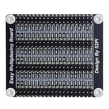
The 52Pi T-Type GPIO Extension Board (Manufacturer Part ID: EP-0089) is a versatile GPIO expansion module designed specifically for Raspberry Pi boards. It provides a convenient way to access and expand the GPIO pins of the Raspberry Pi, making it easier to connect sensors, modules, and other peripherals. The T-shaped design ensures a compact and organized layout, ideal for prototyping and development.
Explore Projects Built with 52Pi T-Type GPIO Extension Board
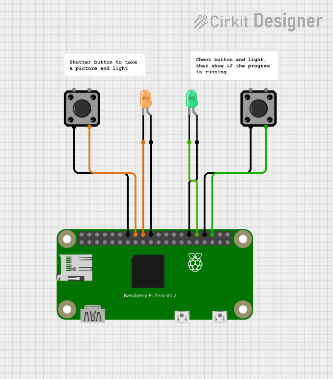

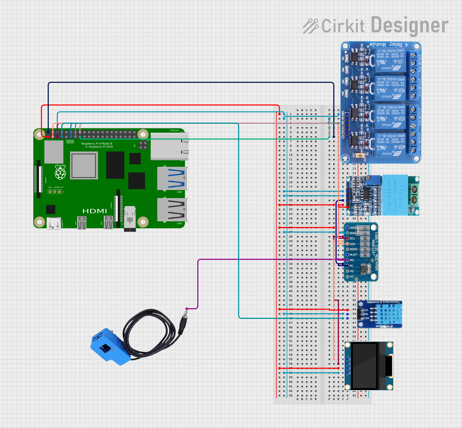

Explore Projects Built with 52Pi T-Type GPIO Extension Board
Common Applications and Use Cases
- Prototyping with Raspberry Pi GPIO pins
- Connecting multiple sensors and modules
- Educational projects and learning GPIO programming
- Building IoT devices and smart systems
- Simplifying access to GPIO pins for breadboard use
Technical Specifications
The following table outlines the key technical details of the 52Pi T-Type GPIO Extension Board:
| Specification | Details |
|---|---|
| Manufacturer | 52Pi Technology Co., Ltd. |
| Part ID | EP-0089 |
| Compatibility | Raspberry Pi models with a 40-pin GPIO header |
| GPIO Pinout | 40-pin GPIO layout, fully compatible with Raspberry Pi GPIO configuration |
| Dimensions | 65mm x 56mm x 15mm |
| Material | PCB with gold-plated contacts |
| Operating Voltage | 3.3V (from Raspberry Pi GPIO header) |
| Breadboard Compatibility | Standard 830-point breadboards |
Pin Configuration and Descriptions
The 52Pi T-Type GPIO Extension Board replicates the Raspberry Pi's 40-pin GPIO header. Below is the pinout configuration:
| Pin Number | Pin Name | Description |
|---|---|---|
| 1 | 3.3V | Power supply (3.3V) |
| 2 | 5V | Power supply (5V) |
| 3 | GPIO2 (SDA1) | I2C Data |
| 4 | 5V | Power supply (5V) |
| 5 | GPIO3 (SCL1) | I2C Clock |
| 6 | GND | Ground |
| ... | ... | ... (follows Raspberry Pi GPIO pinout) |
For the full pinout, refer to the Raspberry Pi GPIO documentation, as the extension board mirrors the standard layout.
Usage Instructions
How to Use the Component in a Circuit
- Connect the Extension Board: Attach the 52Pi T-Type GPIO Extension Board to the Raspberry Pi's 40-pin GPIO header. Ensure proper alignment to avoid damaging the pins.
- Mount on a Breadboard: Place the extension board onto a standard 830-point breadboard. The T-shaped design allows easy access to all GPIO pins on both sides of the breadboard.
- Connect Peripherals: Use jumper wires to connect sensors, modules, or other components to the GPIO pins as needed.
- Power the Raspberry Pi: Supply power to the Raspberry Pi, which will also power the extension board.
Important Considerations and Best Practices
- Voltage Levels: The GPIO pins operate at 3.3V. Avoid connecting components that require higher voltages directly to the GPIO pins.
- Pin Mapping: Double-check the pin mapping to ensure correct connections. Incorrect wiring can damage the Raspberry Pi or connected components.
- Static Precautions: Handle the board with care to avoid static discharge, which can damage the GPIO pins.
- Avoid Overloading: Do not exceed the current limits of the GPIO pins. Use external power supplies for high-power components.
Example Code for Raspberry Pi
Below is an example Python script to blink an LED connected to GPIO17 (pin 11) using the 52Pi T-Type GPIO Extension Board:
Import the necessary library for GPIO control
import RPi.GPIO as GPIO import time
Set the GPIO mode to BCM (Broadcom pin numbering)
GPIO.setmode(GPIO.BCM)
Define the GPIO pin for the LED
LED_PIN = 17
Set up the LED pin as an output
GPIO.setup(LED_PIN, GPIO.OUT)
try: while True: GPIO.output(LED_PIN, GPIO.HIGH) # Turn the LED on time.sleep(1) # Wait for 1 second GPIO.output(LED_PIN, GPIO.LOW) # Turn the LED off time.sleep(1) # Wait for 1 second except KeyboardInterrupt: # Clean up GPIO settings when the script is interrupted GPIO.cleanup()
Notes:
- Connect the LED's anode (long leg) to GPIO17 (pin 11) and the cathode (short leg) to a resistor (e.g., 330Ω), which is then connected to GND.
- Install the
RPi.GPIOlibrary if not already installed:sudo apt-get install python3-rpi.gpio.
Troubleshooting and FAQs
Common Issues Users Might Face
Extension Board Not Detected:
- Ensure the board is properly aligned with the Raspberry Pi's GPIO header.
- Check for bent or damaged pins.
Components Not Working:
- Verify the wiring and connections to the GPIO pins.
- Ensure the correct GPIO pin numbers are used in the code.
Short Circuits:
- Inspect the breadboard for accidental short circuits caused by misplaced wires or components.
Overheating:
- Avoid overloading the GPIO pins. Use external power supplies for high-power devices.
Solutions and Tips for Troubleshooting
- Use a multimeter to check for continuity and proper voltage levels on the GPIO pins.
- Test the Raspberry Pi GPIO pins without the extension board to rule out issues with the Raspberry Pi itself.
- Refer to the Raspberry Pi GPIO pinout diagram to ensure correct connections.
By following this documentation, users can effectively utilize the 52Pi T-Type GPIO Extension Board for their Raspberry Pi projects.