How to Use NodeESP32-C3: Examples, Pinouts, and Specs
Introduction
The NodeESP32-C3 is a versatile development board that harnesses the capabilities of the ESP32-C3 microcontroller. This board is designed for Internet of Things (IoT) applications, providing a compact solution with Wi-Fi connectivity. It is ideal for hobbyists, educators, and professionals looking to prototype and develop wireless projects.
Explore Projects Built with NodeESP32-C3

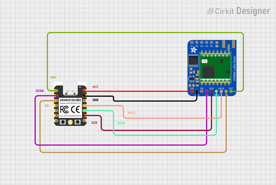
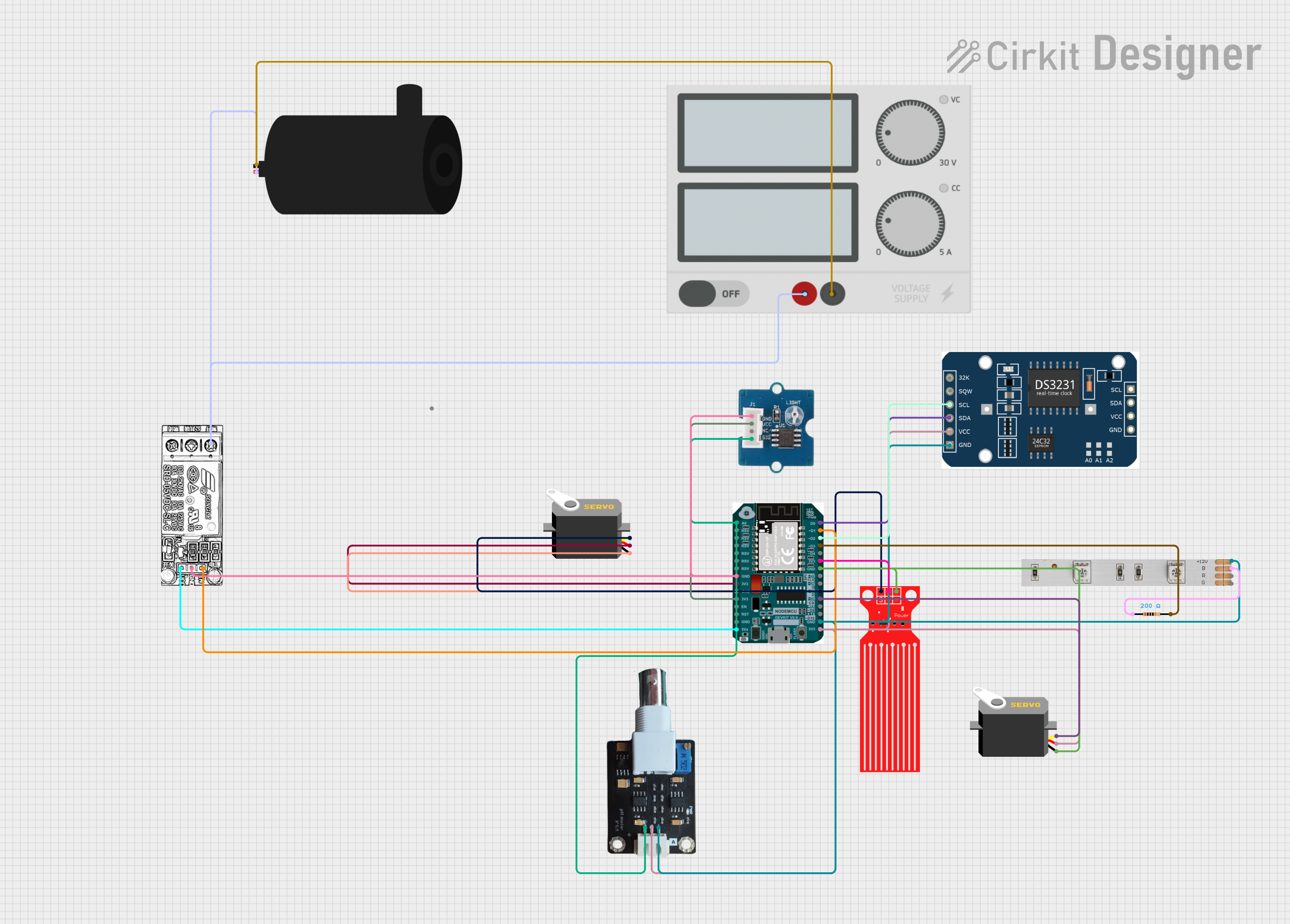
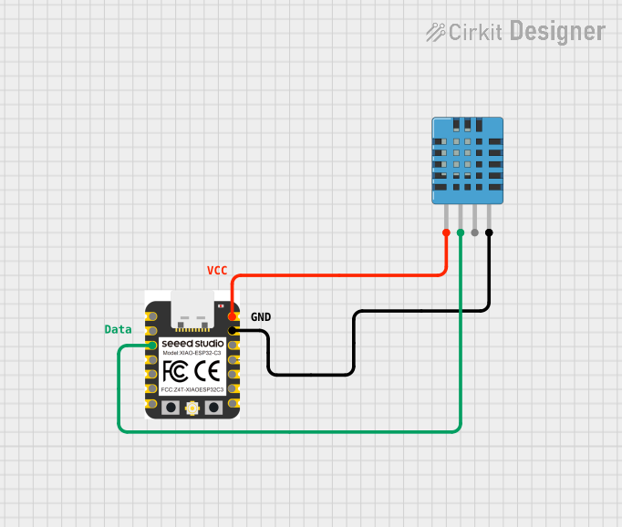
Explore Projects Built with NodeESP32-C3
Common Applications and Use Cases
- Smart home devices
- Wireless sensors and actuators
- IoT prototyping
- Remote monitoring systems
- Educational projects and learning platforms
Technical Specifications
The NodeESP32-C3 development board is built around the ESP32-C3 microcontroller, which is a low-power system on a chip (SoC) featuring Wi-Fi connectivity. Below are the key technical specifications:
- Microcontroller: ESP32-C3
- Operating Voltage: 3.3V
- Input Voltage (recommended): 5V via micro USB
- Digital I/O Pins: 22
- Analog Input Pins: 6
- Flash Memory: 4MB
- SRAM: 400 KB
- Wi-Fi: 802.11 b/g/n (2.4 GHz)
- Bluetooth: BLE 5.0
- Clock Speed: 160 MHz
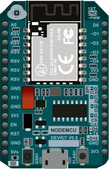
Pin Configuration and Descriptions
| Pin Number | Function | Description |
|---|---|---|
| 1 | 3V3 | 3.3V power supply pin |
| 2 | GND | Ground |
| 3-14 | GPIO0 - GPIO11 | General-purpose input/output pins |
| 15 | ADC1 - ADC6 | Analog-to-digital converter inputs |
| 16 | TX0 | UART transmit pin |
| 17 | RX0 | UART receive pin |
| 18 | VIN | Input voltage for battery or external power |
| 19 | EN | Chip enable, active high |
| 20 | GND | Ground |
| 21 | 5V | 5V power supply pin via USB |
Usage Instructions
Integrating NodeESP32-C3 into a Circuit
- Powering the Board: Connect the micro USB cable to the board and a 5V USB power source.
- Connecting I/O Devices: Attach sensors, actuators, or other peripherals to the GPIO pins.
- Programming: Use the Arduino IDE or other development environments to write and upload code to the board.
Important Considerations and Best Practices
- Ensure that the input voltage does not exceed the recommended 5V to prevent damage.
- When interfacing with other components, make sure they are compatible with the board's 3.3V logic levels.
- Use a current limiting resistor when connecting LEDs to GPIO pins.
- Avoid drawing more than 12 mA from any GPIO pin.
- For Wi-Fi functionality, ensure that the antenna area is not obstructed.
Example Code for Arduino UNO
Below is a simple example code that connects the NodeESP32-C3 to a Wi-Fi network. This code is written for the Arduino IDE.
#include <WiFi.h>

// Replace with your network credentials
const char* ssid = "your_SSID";
const char* password = "your_PASSWORD";

void setup() {
  Serial.begin(115200);

  // Start Wi-Fi connection
  WiFi.begin(ssid, password);

  while (WiFi.status() != WL_CONNECTED) {
    delay(500);
    Serial.print(".");
  }

  // Once connected, print the IP address
  Serial.println("");
  Serial.println("WiFi connected.");
  Serial.println("IP address: ");
  Serial.println(WiFi.localIP());
}

void loop() {
  // Nothing to do here
}
Troubleshooting and FAQs
Common Issues
- Board not connecting to Wi-Fi: Ensure the SSID and password are correct. Check the signal strength and router settings.
- Cannot upload code: Verify the correct board and port are selected in the IDE. Ensure the USB cable is properly connected and the board is powered on.
- GPIO pin not responding: Check for proper pin initialization in the code. Ensure there is no physical damage to the board.
Solutions and Tips for Troubleshooting
- Reset the Board: Press the EN button to reset the board, which can resolve some issues.
- Serial Monitor: Use the Serial Monitor in the Arduino IDE to debug and print out messages from the board.
- Update Firmware: Ensure the ESP32-C3 board package is up to date in the Arduino IDE.
FAQs
Q: Can the NodeESP32-C3 be powered by a battery? A: Yes, it can be powered using the VIN pin with a recommended voltage of 3.7V to 5V.
Q: Does the board have onboard LED? A: Yes, most NodeESP32-C3 boards come with an onboard LED, typically connected to GPIO2.
Q: How do I connect to Bluetooth devices?
A: The ESP32-C3 supports BLE; you can use the NimBLE-Arduino library for Bluetooth functionality.
Q: Can I use the Arduino IDE for programming the NodeESP32-C3? A: Yes, the Arduino IDE can be used after installing the ESP32 board package.
For further assistance, consult the community forums or the manufacturer's support resources.