Cirkit Designer Logo
Cirkit Designer
Your all-in-one circuit design IDE
Home / 
Component Documentation

How to Use Ethernet Pro: Examples, Pinouts, and Specs

Image of Ethernet Pro
Cirkit Designer LogoDesign with Ethernet Pro in Cirkit Designer

Introduction

The Ethernet Pro is an Arduino-compatible shield designed to enable network connectivity for Arduino boards. By providing a standard RJ45 Ethernet jack, it allows Arduino projects to connect to wired networks, enabling functionalities such as network communication, remote control, and data logging. Common applications include home automation, IoT devices, and networked sensors.

Explore Projects Built with Ethernet Pro

Use Cirkit Designer to design, explore, and prototype these projects online. Some projects support real-time simulation. Click "Open Project" to start designing instantly!
ESP32 and W5500 Ethernet Module Controlled 8-Channel Relay
Image of ESP32 38Pin 8 Channel Relay USB-C: A project utilizing Ethernet Pro in a practical application
This circuit enables Ethernet connectivity and device control through an ESP32 microcontroller. It uses the W5500 Ethernet module for network communication and controls an 8-channel relay module for switching external devices or loads.
Cirkit Designer LogoOpen Project in Cirkit Designer
Raspberry Pi 5 Ethernet Module Integration for Enhanced Connectivity
Image of w5500: A project utilizing Ethernet Pro in a practical application
This circuit connects a Raspberry Pi 5 to a W5500 Ethernet module, enabling Ethernet connectivity. The Raspberry Pi communicates with the W5500 via SPI interface, and a resistor is used to manage the reset signal for the Ethernet module.
Cirkit Designer LogoOpen Project in Cirkit Designer
Optiplex Micro and PoE Camera Surveillance System with Ethernet Switching
Image of Engine Mounts Wiring: A project utilizing Ethernet Pro in a practical application
This circuit describes a networked system where an Optiplex Micro computer is powered by a PC Power Supply and connected to a PC Screen via HDMI for display output. The computer is networked through an Ethernet Switch, which also connects to two PoE Cameras and a Toyopuc PLC. The Ethernet Switch is powered by a PoE PSU 48V DC, and all AC-powered devices are connected to a common 220V AC source.
Cirkit Designer LogoOpen Project in Cirkit Designer
ESP8266 NodeMCU with LoRa and RS-485 Communication and Ethernet Connectivity
Image of Wiring Diagram LoRa: A project utilizing Ethernet Pro in a practical application
This circuit serves as a multi-protocol communication hub featuring two ESP8266 NodeMCUs for processing, each connected to a LoRa Ra-02 SX1278 for long-range wireless communication. One NodeMCU is also connected to an RS-485 module for serial communication and a W5500 Ethernet module for network connectivity, with MB102 modules supplying power.
Cirkit Designer LogoOpen Project in Cirkit Designer

Explore Projects Built with Ethernet Pro

Use Cirkit Designer to design, explore, and prototype these projects online. Some projects support real-time simulation. Click "Open Project" to start designing instantly!
Image of ESP32 38Pin 8 Channel Relay USB-C: A project utilizing Ethernet Pro in a practical application
ESP32 and W5500 Ethernet Module Controlled 8-Channel Relay
This circuit enables Ethernet connectivity and device control through an ESP32 microcontroller. It uses the W5500 Ethernet module for network communication and controls an 8-channel relay module for switching external devices or loads.
Cirkit Designer LogoOpen Project in Cirkit Designer
Image of w5500: A project utilizing Ethernet Pro in a practical application
Raspberry Pi 5 Ethernet Module Integration for Enhanced Connectivity
This circuit connects a Raspberry Pi 5 to a W5500 Ethernet module, enabling Ethernet connectivity. The Raspberry Pi communicates with the W5500 via SPI interface, and a resistor is used to manage the reset signal for the Ethernet module.
Cirkit Designer LogoOpen Project in Cirkit Designer
Image of Engine Mounts Wiring: A project utilizing Ethernet Pro in a practical application
Optiplex Micro and PoE Camera Surveillance System with Ethernet Switching
This circuit describes a networked system where an Optiplex Micro computer is powered by a PC Power Supply and connected to a PC Screen via HDMI for display output. The computer is networked through an Ethernet Switch, which also connects to two PoE Cameras and a Toyopuc PLC. The Ethernet Switch is powered by a PoE PSU 48V DC, and all AC-powered devices are connected to a common 220V AC source.
Cirkit Designer LogoOpen Project in Cirkit Designer
Image of Wiring Diagram LoRa: A project utilizing Ethernet Pro in a practical application
ESP8266 NodeMCU with LoRa and RS-485 Communication and Ethernet Connectivity
This circuit serves as a multi-protocol communication hub featuring two ESP8266 NodeMCUs for processing, each connected to a LoRa Ra-02 SX1278 for long-range wireless communication. One NodeMCU is also connected to an RS-485 module for serial communication and a W5500 Ethernet module for network connectivity, with MB102 modules supplying power.
Cirkit Designer LogoOpen Project in Cirkit Designer

Technical Specifications

Key Technical Details

  • Network Connector: RJ45 Ethernet jack
  • Supported Protocols: TCP/IP, UDP, DHCP, DNS, HTTP, Ethernet
  • Network Speeds: 10/100 Mbps (auto-selection)
  • Operating Voltage: 5V (supplied by the Arduino board)
  • Current Consumption: Typical 120 mA; Maximum 170 mA
  • PCB Size: Standard Arduino shield form factor

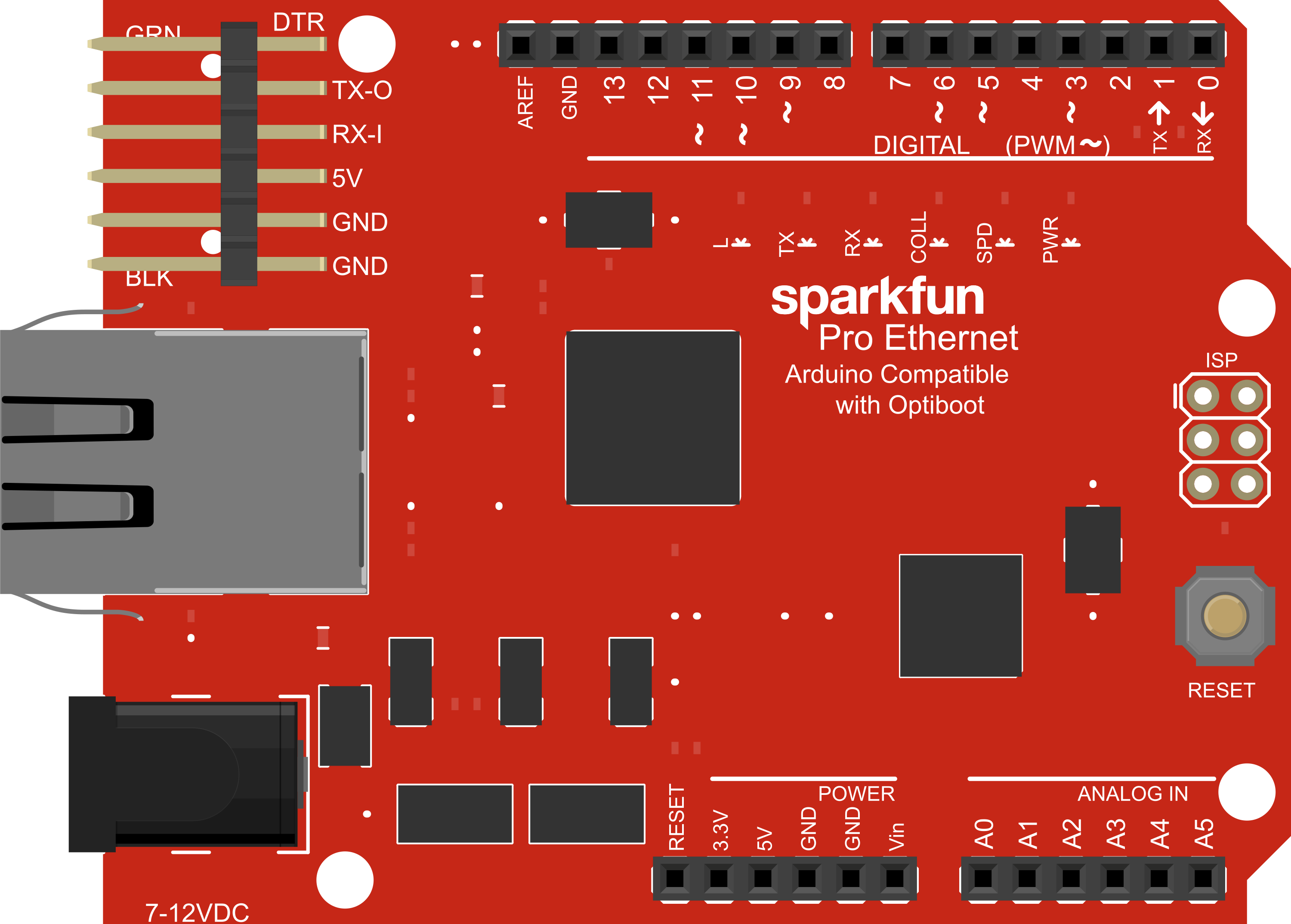
Pin Configuration and Descriptions

Pin Number Function Description
1 INT Interrupt output, active low
2 RESET Reset input, active low
10 SS SPI Slave Select, active low
11 MOSI SPI Master Out Slave In
12 MISO SPI Master In Slave Out
13 SCK SPI Serial Clock
- GND Ground
- 5V 5V Power supply from Arduino

Usage Instructions

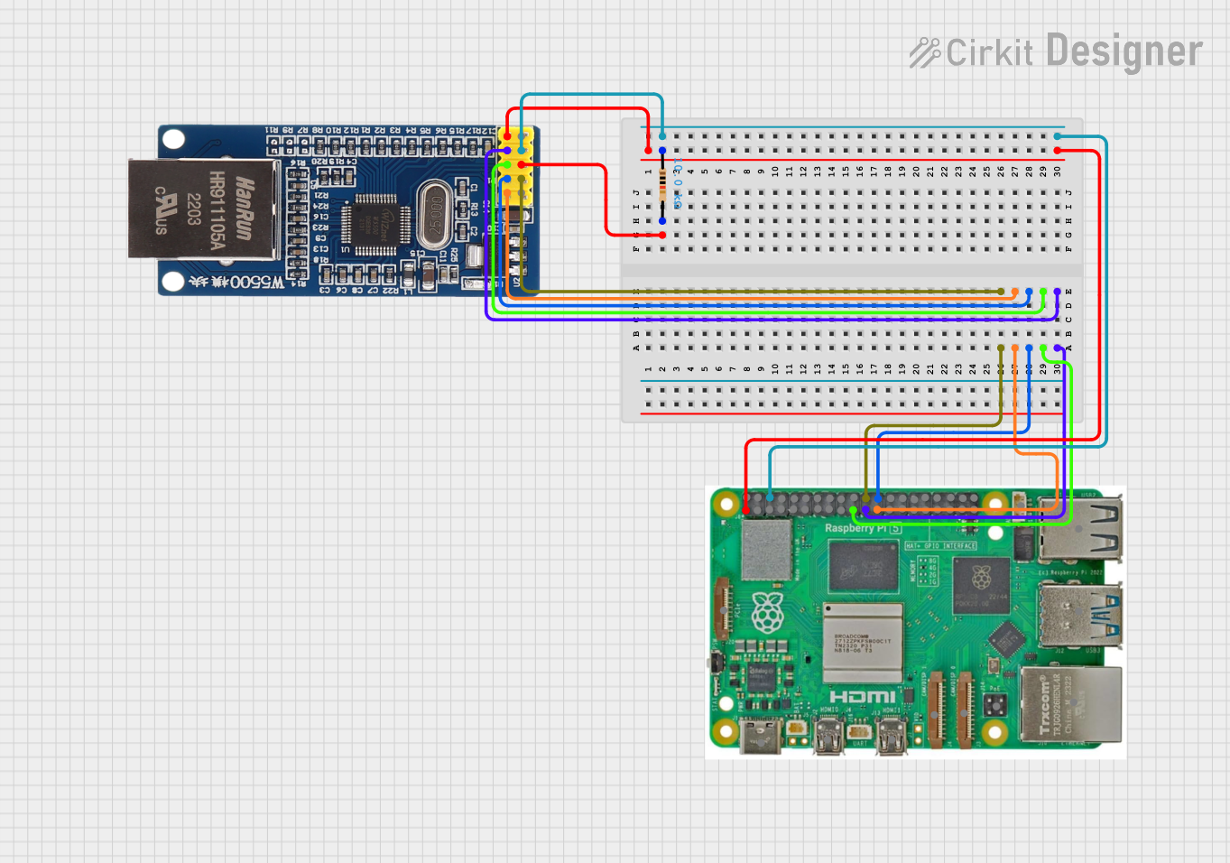
Connecting the Ethernet Pro to an Arduino

  1. Power off your Arduino board.
  2. Align the Ethernet Pro shield pins with the corresponding headers on the Arduino.
  3. Gently press down on the Ethernet Pro shield until it is firmly seated.
  4. Connect an Ethernet cable from the Ethernet Pro's RJ45 jack to your network switch or router.

Programming the Ethernet Pro

To use the Ethernet Pro with an Arduino, include the Ethernet library in your sketches:

#include <Ethernet.h>

Here's a simple example to initialize the Ethernet shield:

#include <SPI.h>
#include <Ethernet.h>

// MAC address for your Ethernet shield
byte mac[] = { 0xDE, 0xAD, 0xBE, 0xEF, 0xFE, 0xED };

void setup() {
  // Open serial communications
  Serial.begin(9600);

  // Start the Ethernet connection
  if (Ethernet.begin(mac) == 0) {
    Serial.println("Failed to configure Ethernet using DHCP");
    // No point in proceeding, loop forever
    for (;;)
      ;
  }
  Serial.println("Ethernet configured via DHCP");
  Serial.print("My IP address: ");
  Serial.println(Ethernet.localIP());
}

void loop() {
  // Main code would go here
}

Best Practices

  • Always use a static anti-static wristband when handling the Ethernet Pro to prevent electrostatic discharge damage.
  • Ensure the Ethernet cable is a standard Cat5/Cat6 with proper RJ45 connectors.
  • Avoid placing the Ethernet Pro near high voltage or high current devices to minimize interference.

Troubleshooting and FAQs

Common Issues

  • No Network Connectivity: Ensure the Ethernet cable is properly connected and the network is operational.
  • IP Address Not Assigned: Check if the DHCP server is operational or configure a static IP address.
  • Shield Not Recognized: Make sure the shield is properly seated on the Arduino and the correct library is included in the sketch.

Solutions and Tips

  • Resetting the Shield: Use the reset button on the shield or power cycle the Arduino to reset the Ethernet Pro.
  • Static IP Configuration: If DHCP is not available, configure a static IP by modifying the Ethernet.begin() parameters.
  • Network Diagnostics: Use network tools like ping to test connectivity and ensure the network is configured correctly.

FAQs

  • Can the Ethernet Pro be used with Arduino Mega or Leonardo? Yes, the Ethernet Pro is compatible with any Arduino board that has an ICSP header and conforms to the shield form factor.

  • Does the Ethernet Pro support Power over Ethernet (PoE)? No, the Ethernet Pro does not support PoE natively. An external PoE module would be required.

  • Can I connect multiple Ethernet Pro shields to one Arduino? No, the SPI interface used by the Ethernet Pro does not support multiple Ethernet controllers on the same bus.

For further assistance, consult the Arduino Ethernet library documentation and the Ethernet Pro manufacturer's resources.