
How to Use Hall Sensor Analog: Examples, Pinouts, and Specs
 Design with Hall Sensor Analog in Cirkit Designer
Introduction
A Hall sensor analog is a device that detects the presence and strength of a magnetic field. It outputs a continuous voltage signal proportional to the magnetic field strength. This makes it highly versatile for a variety of applications, including:
- Position sensing: Detecting the position of a magnet or magnetic object.
- Speed detection: Measuring the rotational speed of motors or wheels.
- Current measurement: Sensing current flow in a conductor using the magnetic field generated by the current.
Hall sensor analogs are widely used in automotive systems, industrial equipment, and consumer electronics due to their reliability and precision.
Explore Projects Built with Hall Sensor Analog
 Open Project in Cirkit Designer
 Open Project in Cirkit Designer
 Open Project in Cirkit Designer
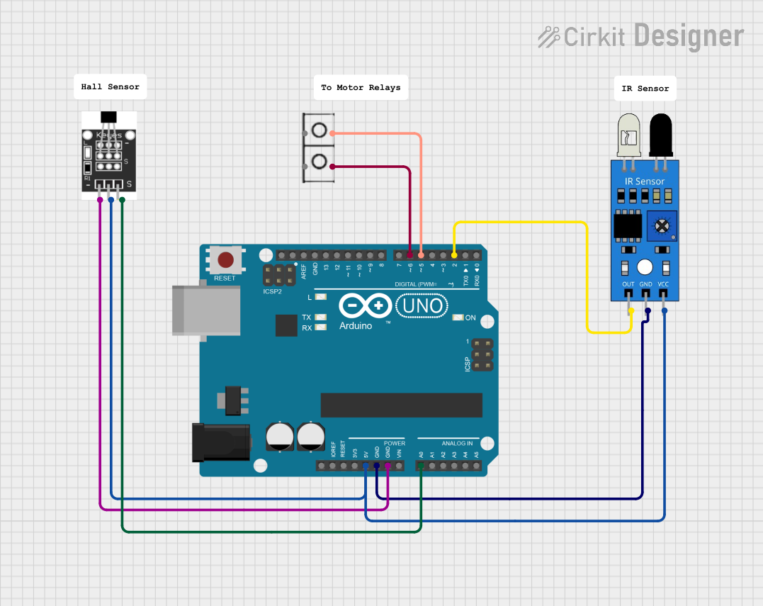 Open Project in Cirkit Designer
Explore Projects Built with Hall Sensor Analog
Open Project in Cirkit DesignerOpen Project in Cirkit DesignerOpen Project in Cirkit DesignerOpen Project in Cirkit DesignerTechnical Specifications
Below are the key technical details for a typical Hall sensor analog:
| Parameter | Value |
|---|---|
| Supply Voltage (Vcc) | 3.3V to 5V |
| Output Voltage Range | 0.2V to 4.8V (proportional to field strength) |
| Current Consumption | 5 mA (typical) |
| Magnetic Sensitivity | 1.3 mV/Gauss (typical) |
| Operating Temperature | -40°C to +85°C |
| Response Time | < 10 µs |
Pin Configuration and Descriptions
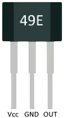
The Hall sensor analog typically has three pins:
| Pin | Name | Description |
|---|---|---|
| 1 | Vcc | Power supply input (3.3V to 5V). |
| 2 | GND | Ground connection. |
| 3 | OUT | Analog output voltage proportional to magnetic field strength. |
Usage Instructions
How to Use the Component in a Circuit
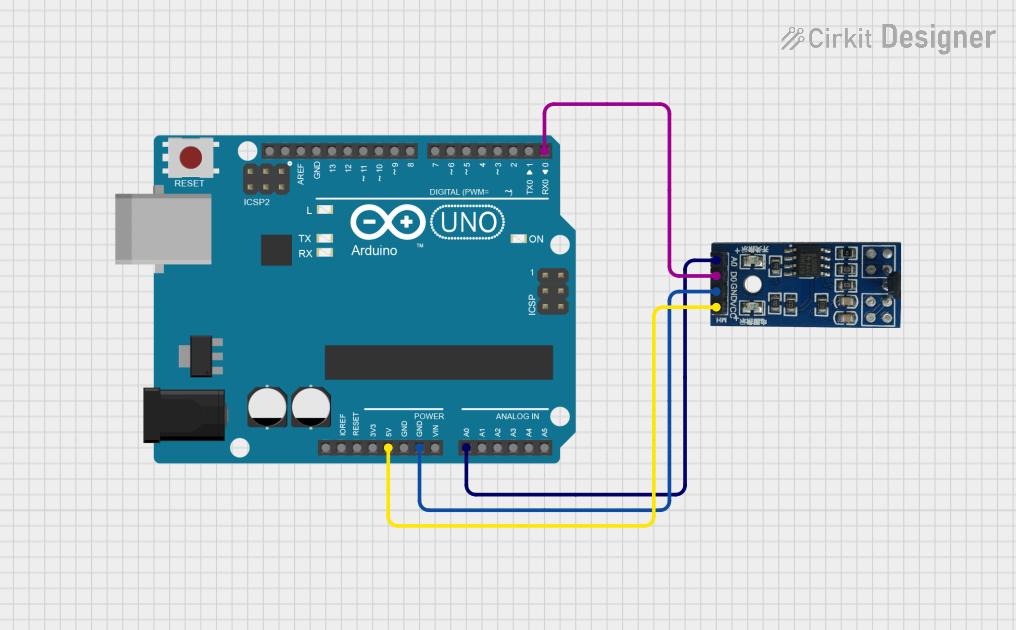
- Power the Sensor: Connect the Vcc pin to a 3.3V or 5V power supply and the GND pin to the ground of your circuit.
- Read the Output: Connect the OUT pin to an analog input pin of a microcontroller (e.g., Arduino) or an ADC (Analog-to-Digital Converter) to measure the output voltage.
- Place the Magnet: Position a magnet near the sensor. The output voltage will vary depending on the strength and polarity of the magnetic field.
Important Considerations and Best Practices
- Magnetic Field Orientation: Ensure the magnetic field is perpendicular to the sensor for optimal sensitivity.
- Noise Filtering: Add a small capacitor (e.g., 0.1 µF) between the OUT pin and GND to filter out noise in the output signal.
- Avoid Overvoltage: Do not exceed the maximum supply voltage (5V) to prevent damage to the sensor.
- Temperature Effects: Be aware of temperature variations, as they may slightly affect the sensor's output.
Example Code for Arduino UNO
Below is an example of how to use a Hall sensor analog with an Arduino UNO to read and display the magnetic field strength:
// Define the analog pin connected to the Hall sensor's OUT pin
const int hallSensorPin = A0;

void setup() {
  Serial.begin(9600); // Initialize serial communication at 9600 baud
  pinMode(hallSensorPin, INPUT); // Set the Hall sensor pin as input
}

void loop() {
  int sensorValue = analogRead(hallSensorPin);
  // Read the analog value from the Hall sensor

  float voltage = sensorValue * (5.0 / 1023.0);
  // Convert the analog reading to voltage (5V reference, 10-bit ADC)

  Serial.print("Magnetic Field Voltage: ");
  Serial.print(voltage);
  Serial.println(" V");

  delay(500); // Wait for 500ms before the next reading
}
Troubleshooting and FAQs
Common Issues Users Might Face
No Output Voltage:
- Cause: Incorrect wiring or no power supply.
- Solution: Double-check the connections and ensure the Vcc pin is connected to a 3.3V or 5V power source.
Fluctuating Output Signal:
- Cause: Electrical noise or unstable power supply.
- Solution: Add a decoupling capacitor (e.g., 0.1 µF) between the OUT pin and GND.
Output Voltage Does Not Change:
- Cause: Magnet is too far from the sensor or not aligned properly.
- Solution: Move the magnet closer to the sensor and ensure it is perpendicular to the sensor's surface.
Sensor Overheating:
- Cause: Exceeding the maximum supply voltage.
- Solution: Verify that the supply voltage is within the specified range (3.3V to 5V).
FAQs
Q: Can I use the Hall sensor analog with a 3.3V microcontroller?
A: Yes, the sensor operates within a supply voltage range of 3.3V to 5V, making it compatible with 3.3V systems.
Q: How do I measure the magnetic field strength in Gauss?
A: Use the sensor's sensitivity rating (e.g., 1.3 mV/Gauss) to calculate the field strength. For example, if the output voltage changes by 13 mV, the field strength is approximately 10 Gauss.
Q: Can the sensor detect both north and south poles of a magnet?
A: Yes, the sensor can detect both poles, and the output voltage will vary depending on the polarity and strength of the magnetic field.
Q: Is the Hall sensor analog suitable for high-speed applications?
A: Yes, with a response time of less than 10 µs, it is suitable for high-speed applications such as motor speed detection.