Cirkit Designer Logo
Cirkit Designer
Your all-in-one circuit design IDE
Home / 
Component Documentation

How to Use nRF52840 ProMicro: Examples, Pinouts, and Specs

Image of nRF52840 ProMicro
Cirkit Designer LogoDesign with nRF52840 ProMicro in Cirkit Designer

Introduction

The nRF52840 ProMicro is a versatile and powerful microcontroller board designed for advanced wireless applications. Based on the Nordic Semiconductor nRF52840 chip, this development board is ideal for Internet of Things (IoT) projects, Bluetooth Low Energy (BLE) applications, and any project requiring a compact, yet feature-rich microcontroller.

Explore Projects Built with nRF52840 ProMicro

Use Cirkit Designer to design, explore, and prototype these projects online. Some projects support real-time simulation. Click "Open Project" to start designing instantly!
Battery-Powered nRF52840 and HT-RA62 Communication Module
Image of NRF52840+HT-RA62: A project utilizing nRF52840 ProMicro in a practical application
This circuit is a wireless communication system powered by a 18650 Li-ion battery, featuring an nRF52840 ProMicro microcontroller and an HT-RA62 transceiver module. The nRF52840 handles the control logic and interfaces with the HT-RA62 for data transmission, while the battery provides the necessary power for the entire setup.
Cirkit Designer LogoOpen Project in Cirkit Designer
Bluetooth-Controlled Robotic Vehicle with Ultrasonic Obstacle Detection and Motion Sensing
Image of 아두이노 드론: A project utilizing nRF52840 ProMicro in a practical application
This circuit features a SparkFun Pro Micro microcontroller interfaced with an L298N DC motor driver to control two DC motors, an HC-SR04 ultrasonic sensor for distance measurement, a Bluetooth module HM-10 for wireless communication, and an MPU-6050 for motion tracking. The Pro Micro is responsible for processing sensor data and managing motor speeds and directions via the motor driver. Power is supplied by a 5V battery connected to the Pro Micro and a separate battery case providing 12V to the motor driver.
Cirkit Designer LogoOpen Project in Cirkit Designer
STM32 and Arduino Pro Mini Based Wireless Data Logger with OLED Display
Image of R8 Controller: A project utilizing nRF52840 ProMicro in a practical application
This circuit integrates multiple microcontrollers (Maple Mini STM32F1, nRF52840 ProMicro, and Arduino Pro Mini) to interface with various peripherals including an SSD1306 OLED display, an SD card module, and a Si4463 RF module. The circuit is designed for data acquisition, storage, and wireless communication, with power supplied through a USB Serial TTL module.
Cirkit Designer LogoOpen Project in Cirkit Designer
Battery-Powered Heart Rate Monitor using Seeed Studio nRF52840 and MAX30102
Image of Senior Design-Circuitry: A project utilizing nRF52840 ProMicro in a practical application
This circuit integrates a Seeed Studio nRF52840 microcontroller with a MAX30102 sensor module. The microcontroller powers the sensor and communicates with it via I2C protocol, enabling functionalities such as heart rate and SpO2 monitoring.
Cirkit Designer LogoOpen Project in Cirkit Designer

Explore Projects Built with nRF52840 ProMicro

Use Cirkit Designer to design, explore, and prototype these projects online. Some projects support real-time simulation. Click "Open Project" to start designing instantly!
Image of NRF52840+HT-RA62: A project utilizing nRF52840 ProMicro in a practical application
Battery-Powered nRF52840 and HT-RA62 Communication Module
This circuit is a wireless communication system powered by a 18650 Li-ion battery, featuring an nRF52840 ProMicro microcontroller and an HT-RA62 transceiver module. The nRF52840 handles the control logic and interfaces with the HT-RA62 for data transmission, while the battery provides the necessary power for the entire setup.
Cirkit Designer LogoOpen Project in Cirkit Designer
Image of 아두이노 드론: A project utilizing nRF52840 ProMicro in a practical application
Bluetooth-Controlled Robotic Vehicle with Ultrasonic Obstacle Detection and Motion Sensing
This circuit features a SparkFun Pro Micro microcontroller interfaced with an L298N DC motor driver to control two DC motors, an HC-SR04 ultrasonic sensor for distance measurement, a Bluetooth module HM-10 for wireless communication, and an MPU-6050 for motion tracking. The Pro Micro is responsible for processing sensor data and managing motor speeds and directions via the motor driver. Power is supplied by a 5V battery connected to the Pro Micro and a separate battery case providing 12V to the motor driver.
Cirkit Designer LogoOpen Project in Cirkit Designer
Image of R8 Controller: A project utilizing nRF52840 ProMicro in a practical application
STM32 and Arduino Pro Mini Based Wireless Data Logger with OLED Display
This circuit integrates multiple microcontrollers (Maple Mini STM32F1, nRF52840 ProMicro, and Arduino Pro Mini) to interface with various peripherals including an SSD1306 OLED display, an SD card module, and a Si4463 RF module. The circuit is designed for data acquisition, storage, and wireless communication, with power supplied through a USB Serial TTL module.
Cirkit Designer LogoOpen Project in Cirkit Designer
Image of Senior Design-Circuitry: A project utilizing nRF52840 ProMicro in a practical application
Battery-Powered Heart Rate Monitor using Seeed Studio nRF52840 and MAX30102
This circuit integrates a Seeed Studio nRF52840 microcontroller with a MAX30102 sensor module. The microcontroller powers the sensor and communicates with it via I2C protocol, enabling functionalities such as heart rate and SpO2 monitoring.
Cirkit Designer LogoOpen Project in Cirkit Designer

Common Applications and Use Cases

  • Wearable devices
  • Wireless sensor networks
  • Smart home automation
  • IoT edge devices
  • Advanced hobbyist projects requiring BLE connectivity

Technical Specifications

Key Technical Details

  • Microcontroller: Nordic Semiconductor nRF52840
  • Operating Voltage: 3.3V
  • Input Voltage: 5V (via USB) or Li-Po (3.7V)
  • Digital I/O Pins: 18
  • PWM Channels: 12
  • Analog Input Channels: 6 (14-bit ADC)
  • UART Ports: 1
  • I2C Interfaces: 1
  • SPI Interfaces: 1
  • Flash Memory: 1MB
  • SRAM: 256KB
  • Clock Speed: 64MHz
  • Connectivity: Bluetooth 5, NFC, Zigbee, Thread
  • USB: Native USB support

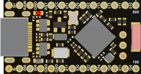
Pin Configuration and Descriptions

Pin Number Function Description
1-18 Digital I/O Digital input/output pins, PWM capable
A0-A5 Analog Input Analog input channels, 14-bit ADC
TXO UART Transmit Transmit pin for serial communication
RXI UART Receive Receive pin for serial communication
SCK SPI Clock Clock pin for SPI communication
MOSI SPI Master Out Master Out Slave In for SPI communication
MISO SPI Master In Master In Slave Out for SPI communication
SDA I2C Data Data line for I2C communication
SCL I2C Clock Clock line for I2C communication
RST Reset Reset pin, active low
GND Ground Ground connection
VIN Voltage Input Input voltage for the board
VUSB USB Voltage Voltage from the USB connection
3V3 3.3V Output Regulated 3.3V output
P0.00-P0.31 GPIO General Purpose I/O pins specific to nRF52840

Usage Instructions

How to Use the Component in a Circuit

  1. Powering the Board:

    • Connect the board to a computer via USB or provide power through the VIN pin.
    • Ensure that the power supply is within the specified voltage range.
  2. Programming the Board:

    • The nRF52840 ProMicro can be programmed using the Arduino IDE or other compatible software.
    • Select the appropriate board and port before uploading your code.
  3. Connecting Peripherals:

    • Use the digital and analog pins to connect sensors, actuators, and other peripherals.
    • For I2C or SPI devices, connect to the respective pins and ensure proper configuration in your code.

Important Considerations and Best Practices

  • Always disconnect the board from power sources before making or altering connections.
  • Observe proper electrostatic discharge (ESD) precautions to avoid damaging the board.
  • When using wireless features, ensure compliance with local regulations regarding radio frequency emissions.

Example Code for Arduino UNO

// Example code to blink an LED on pin 13
#include <Arduino.h>

void setup() {
  pinMode(13, OUTPUT); // Set pin 13 as an output
}

void loop() {
  digitalWrite(13, HIGH); // Turn the LED on
  delay(1000);            // Wait for a second
  digitalWrite(13, LOW);  // Turn the LED off
  delay(1000);            // Wait for a second
}

Troubleshooting and FAQs

Common Issues

  • Board not recognized by computer:

    • Ensure the USB cable is properly connected and the board is powered.
    • Try using a different USB port or cable.
  • Unable to upload code:

    • Check that the correct board and port are selected in the IDE.
    • Press the reset button on the board and attempt to upload again.
  • Wireless functionality not working:

    • Verify that the antenna is properly connected if using an external antenna.
    • Ensure that the wireless protocol and frequency settings in your code match the capabilities of the board.

Solutions and Tips for Troubleshooting

  • Always start by checking connections and ensuring that power is supplied correctly.
  • Consult the board's datasheet and reference manual for detailed information on pin functions and capabilities.
  • Use serial debugging to print out status messages and variable values to the serial monitor for troubleshooting code issues.

FAQs

Q: Can the nRF52840 ProMicro be used with the Arduino IDE? A: Yes, the board is compatible with the Arduino IDE. Make sure to install the necessary board packages and select the correct board from the tools menu.

Q: What wireless protocols does the nRF52840 ProMicro support? A: The board supports Bluetooth 5, NFC, Zigbee, and Thread.

Q: Is it possible to use an external power source instead of USB? A: Yes, you can power the board through the VIN pin using a regulated power source within the specified voltage range.

Q: How can I extend the range of the Bluetooth signal? A: For extended range, consider using an external antenna and ensure that your code is optimized for long-range communication settings.

For further assistance, please refer to the Nordic Semiconductor developer forums or the community around the nRF52840 ProMicro for project-specific advice and support.