
How to Use MOSFET 4 kanal: Examples, Pinouts, and Specs
 Design with MOSFET 4 kanal in Cirkit Designer
Introduction
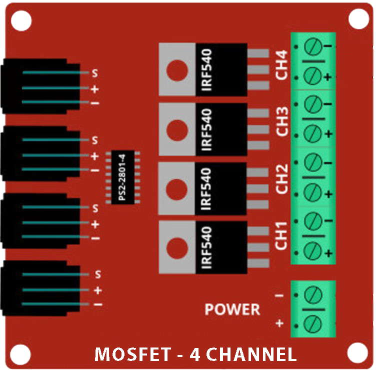
The MOSFET 4 Kanal (IRF9540N), manufactured by Basti, is a 4-channel Metal-Oxide-Semiconductor Field-Effect Transistor (MOSFET) module. It is designed for switching and amplifying electronic signals, enabling efficient control of multiple circuits with a single device. This module is particularly useful in applications requiring high-speed switching, low power loss, and precise control.
Explore Projects Built with MOSFET 4 kanal
 Open Project in Cirkit Designer
 Open Project in Cirkit Designer
 Open Project in Cirkit Designer
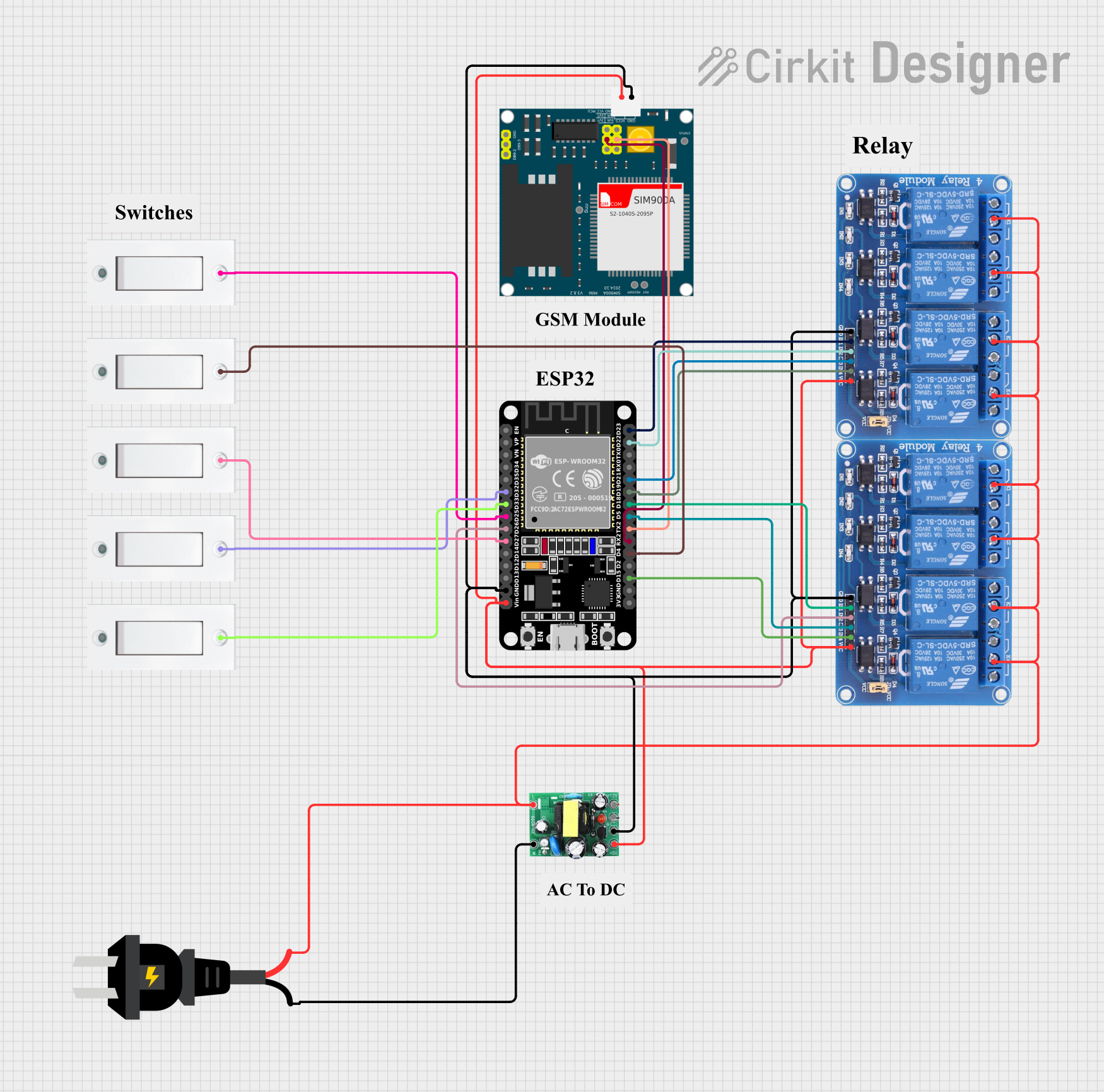 Open Project in Cirkit Designer
Explore Projects Built with MOSFET 4 kanal
Open Project in Cirkit DesignerOpen Project in Cirkit DesignerOpen Project in Cirkit DesignerOpen Project in Cirkit DesignerCommon Applications
- Motor control in robotics and automation
- LED dimming and lighting systems
- Power management in DC circuits
- Signal amplification in audio and RF systems
- General-purpose switching in embedded systems
Technical Specifications
Key Technical Details
| Parameter | Value |
|---|---|
| Manufacturer | Basti |
| Part ID | IRF9540N |
| Number of Channels | 4 |
| MOSFET Type | P-Channel |
| Maximum Drain-Source Voltage (VDS) | -100V |
| Maximum Gate-Source Voltage (VGS) | ±20V |
| Continuous Drain Current (ID) | -23A |
| Power Dissipation | 200W |
| RDS(on) (On Resistance) | 0.117Ω (typical) |
| Operating Temperature | -55°C to +175°C |
| Package Type | TO-220 |
Pin Configuration and Descriptions
Each channel of the MOSFET 4 Kanal module has three pins: Gate (G), Drain (D), and Source (S). Below is the pin configuration for a single channel:
| Pin Name | Description |
|---|---|
| Gate (G) | Controls the MOSFET's switching state. |
| Drain (D) | Connects to the load or circuit being controlled. |
| Source (S) | Connects to the ground or negative terminal. |
The module has four such channels, allowing independent control of four separate circuits.
Usage Instructions
How to Use the Component in a Circuit
- Power Supply: Ensure the power supply voltage does not exceed the maximum VDS (-100V) or VGS (±20V) ratings.
- Gate Control: Use a microcontroller (e.g., Arduino UNO) or a signal generator to control the Gate pin. A voltage of 0V turns the MOSFET off, while a negative voltage (relative to the Source) turns it on.
- Load Connection: Connect the load (e.g., motor, LED) between the Drain pin and the positive terminal of the power supply.
- Source Connection: Connect the Source pin to the ground or negative terminal of the power supply.
Important Considerations and Best Practices
- Gate Resistor: Use a resistor (e.g., 10Ω to 100Ω) between the microcontroller and the Gate pin to limit inrush current and protect the microcontroller.
- Heat Dissipation: Attach a heatsink to the MOSFET module if operating at high currents to prevent overheating.
- Flyback Diode: For inductive loads (e.g., motors), add a flyback diode across the load to protect the MOSFET from voltage spikes.
- Voltage Levels: Ensure the Gate voltage is within the specified range to avoid damaging the MOSFET.
Example: Using with Arduino UNO
Below is an example of controlling a DC motor using one channel of the MOSFET 4 Kanal module and an Arduino UNO.
// Define the MOSFET Gate pin connected to Arduino
const int mosfetGatePin = 9; // Pin 9 controls the MOSFET Gate

void setup() {
  pinMode(mosfetGatePin, OUTPUT); // Set the Gate pin as an output
}

void loop() {
  digitalWrite(mosfetGatePin, HIGH); // Turn the MOSFET on (motor runs)
  delay(1000); // Wait for 1 second
  digitalWrite(mosfetGatePin, LOW);  // Turn the MOSFET off (motor stops)
  delay(1000); // Wait for 1 second
}
Note: Ensure the Gate voltage is within the Arduino's output range (0V to 5V) and use a level shifter if necessary for higher voltages.
Troubleshooting and FAQs
Common Issues and Solutions
MOSFET Overheating
- Cause: High current or insufficient cooling.
- Solution: Attach a heatsink or reduce the load current.
MOSFET Not Switching
- Cause: Insufficient Gate voltage or incorrect wiring.
- Solution: Verify the Gate voltage and ensure proper connections.
Load Not Operating
- Cause: Incorrect load connection or damaged MOSFET.
- Solution: Check the load wiring and test the MOSFET with a multimeter.
Voltage Spikes Damaging the MOSFET
- Cause: Inductive loads without a flyback diode.
- Solution: Add a flyback diode across the load.
FAQs
Q1: Can I use the MOSFET 4 Kanal module with a 3.3V microcontroller?
A1: Yes, but ensure the Gate voltage is sufficient to fully turn on the MOSFET. Use a level shifter if needed.
Q2: What is the maximum current I can draw per channel?
A2: The maximum continuous current per channel is -23A, but ensure proper cooling to avoid overheating.
Q3: Can I control all four channels independently?
A3: Yes, each channel has its own Gate, Drain, and Source pins for independent control.
Q4: Is the module suitable for AC loads?
A4: No, the MOSFET 4 Kanal module is designed for DC loads only.