Cirkit Designer Logo
Cirkit Designer
Your all-in-one circuit design IDE
Home / 
Component Documentation

How to Use 12V DC Motor Encoder: Examples, Pinouts, and Specs

Image of 12V DC Motor Encoder
Cirkit Designer LogoDesign with 12V DC Motor Encoder in Cirkit Designer

Introduction

A 12V DC Motor Encoder is an essential component in robotics and automation, providing precise feedback on motor position, speed, and direction. This feedback is crucial for applications requiring accurate motor control, such as in conveyor belts, positioning systems, and robotic arms. By integrating an encoder with a DC motor, users can achieve closed-loop control, enhancing the performance of their systems.

Explore Projects Built with 12V DC Motor Encoder

Use Cirkit Designer to design, explore, and prototype these projects online. Some projects support real-time simulation. Click "Open Project" to start designing instantly!
Arduino-Controlled DC Motor with Encoder Feedback and Adjustable Speed
Image of gear motor: A project utilizing 12V DC Motor Encoder in a practical application
This circuit controls a gear motor with an integrated encoder using an L298N DC motor driver, which is interfaced with an Arduino Mega 2560 microcontroller. The motor's power is supplied by a 12V power source, which is also connected to an XL4015 DC Buck Step-down converter to provide a regulated 5V supply to the Arduino. The encoder outputs are connected to the Arduino for position or speed feedback, and the Arduino is programmed to manage the motor's speed and direction.
Cirkit Designer LogoOpen Project in Cirkit Designer
Arduino UNO and L298N Motor Driver Controlled DC Motor with Encoder
Image of 460proj: A project utilizing 12V DC Motor Encoder in a practical application
This circuit controls a DC motor with an encoder using an Arduino UNO and an L298N motor driver. The Arduino reads encoder signals to determine motor position and velocity, and adjusts motor speed and direction based on a control algorithm implemented in the provided code. Power is supplied by a 12V battery.
Cirkit Designer LogoOpen Project in Cirkit Designer
Arduino UNO Controlled DC Motor with Encoder and Cytron Driver - Battery Powered
Image of 창종설: A project utilizing 12V DC Motor Encoder in a practical application
This circuit is designed to control a DC motor with an encoder using an Arduino UNO and a Cytron motor driver. The Arduino UNO provides control signals to the Cytron driver, which in turn drives the motor, while the encoder feedback is used for precise motor control. Power is supplied by a 12V battery.
Cirkit Designer LogoOpen Project in Cirkit Designer
Arduino Mega 2560 Controlled Quadruple DC Motor System with Encoders
Image of N20 CONNECTION TO MEGA: A project utilizing 12V DC Motor Encoder in a practical application
This circuit is designed to control four DC motors with encoders using two L298N motor driver modules, which are interfaced with an Arduino Mega 2560. The Arduino provides PWM signals to control the speed and direction of the motors, while also reading the encoder signals to monitor their rotation. A 12V battery powers the motor drivers and motors, with the ground connected to the Arduino for a common reference.
Cirkit Designer LogoOpen Project in Cirkit Designer

Explore Projects Built with 12V DC Motor Encoder

Use Cirkit Designer to design, explore, and prototype these projects online. Some projects support real-time simulation. Click "Open Project" to start designing instantly!
Image of gear motor: A project utilizing 12V DC Motor Encoder in a practical application
Arduino-Controlled DC Motor with Encoder Feedback and Adjustable Speed
This circuit controls a gear motor with an integrated encoder using an L298N DC motor driver, which is interfaced with an Arduino Mega 2560 microcontroller. The motor's power is supplied by a 12V power source, which is also connected to an XL4015 DC Buck Step-down converter to provide a regulated 5V supply to the Arduino. The encoder outputs are connected to the Arduino for position or speed feedback, and the Arduino is programmed to manage the motor's speed and direction.
Cirkit Designer LogoOpen Project in Cirkit Designer
Image of 460proj: A project utilizing 12V DC Motor Encoder in a practical application
Arduino UNO and L298N Motor Driver Controlled DC Motor with Encoder
This circuit controls a DC motor with an encoder using an Arduino UNO and an L298N motor driver. The Arduino reads encoder signals to determine motor position and velocity, and adjusts motor speed and direction based on a control algorithm implemented in the provided code. Power is supplied by a 12V battery.
Cirkit Designer LogoOpen Project in Cirkit Designer
Image of 창종설: A project utilizing 12V DC Motor Encoder in a practical application
Arduino UNO Controlled DC Motor with Encoder and Cytron Driver - Battery Powered
This circuit is designed to control a DC motor with an encoder using an Arduino UNO and a Cytron motor driver. The Arduino UNO provides control signals to the Cytron driver, which in turn drives the motor, while the encoder feedback is used for precise motor control. Power is supplied by a 12V battery.
Cirkit Designer LogoOpen Project in Cirkit Designer
Image of N20 CONNECTION TO MEGA: A project utilizing 12V DC Motor Encoder in a practical application
Arduino Mega 2560 Controlled Quadruple DC Motor System with Encoders
This circuit is designed to control four DC motors with encoders using two L298N motor driver modules, which are interfaced with an Arduino Mega 2560. The Arduino provides PWM signals to control the speed and direction of the motors, while also reading the encoder signals to monitor their rotation. A 12V battery powers the motor drivers and motors, with the ground connected to the Arduino for a common reference.
Cirkit Designer LogoOpen Project in Cirkit Designer

Technical Specifications

General Specifications

  • Operating Voltage: 12V DC
  • Output: Quadrature encoder signals (A and B)
  • Pulses per Revolution (PPR): Typically 100 to 2000 (varies by model)
  • Maximum Rotational Speed: Depends on the motor specifications
  • Operating Temperature Range: -10°C to +70°C (14°F to 158°F)

Pin Configuration and Descriptions

Pin Number Description Notes
1 Vcc (Power Supply) Connect to 12V DC
2 Ground (GND) Connect to system ground
3 Encoder Output A Quadrature output A
4 Encoder Output B Quadrature output B
5 Index (Optional) Pulse per revolution (if present)
6 Motor + Connect to positive motor lead
7 Motor - Connect to negative motor lead

Note: The pin configuration may vary depending on the manufacturer. Always refer to the datasheet of the specific model you are using.

Usage Instructions

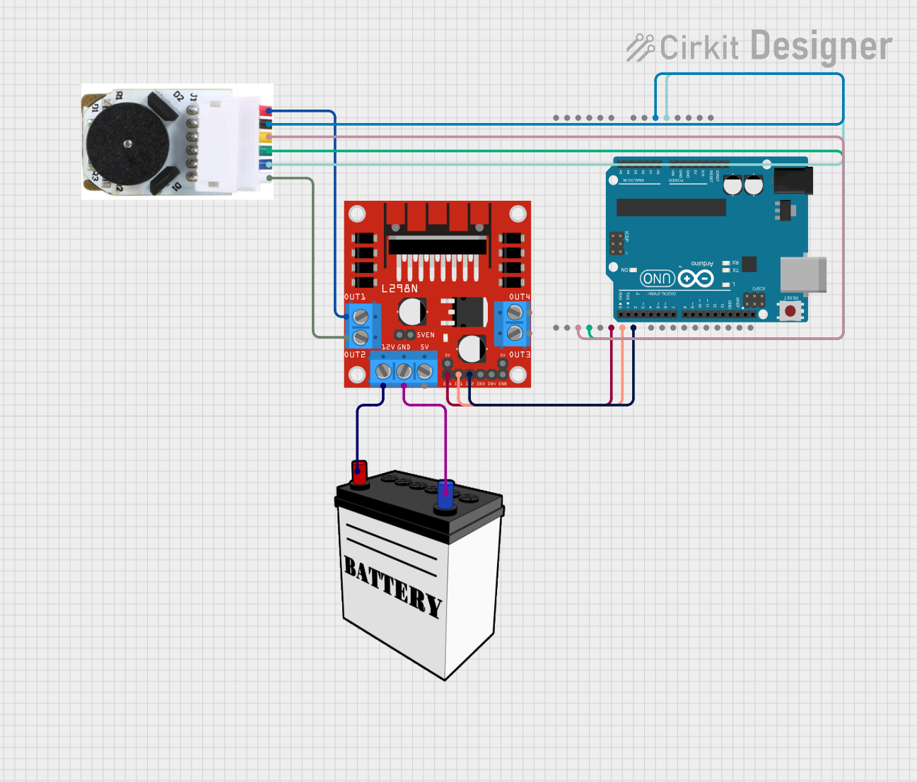
Wiring the Encoder to a Circuit

  1. Connect the Vcc pin to a 12V DC power supply.
  2. Connect the GND pin to the common ground in your circuit.
  3. Connect Encoder Output A and B to the input pins on your microcontroller or interface board.
  4. If available, connect the Index pin to another input pin for additional feedback.
  5. Connect Motor + and Motor - to the motor driver or H-bridge circuit controlling the motor.

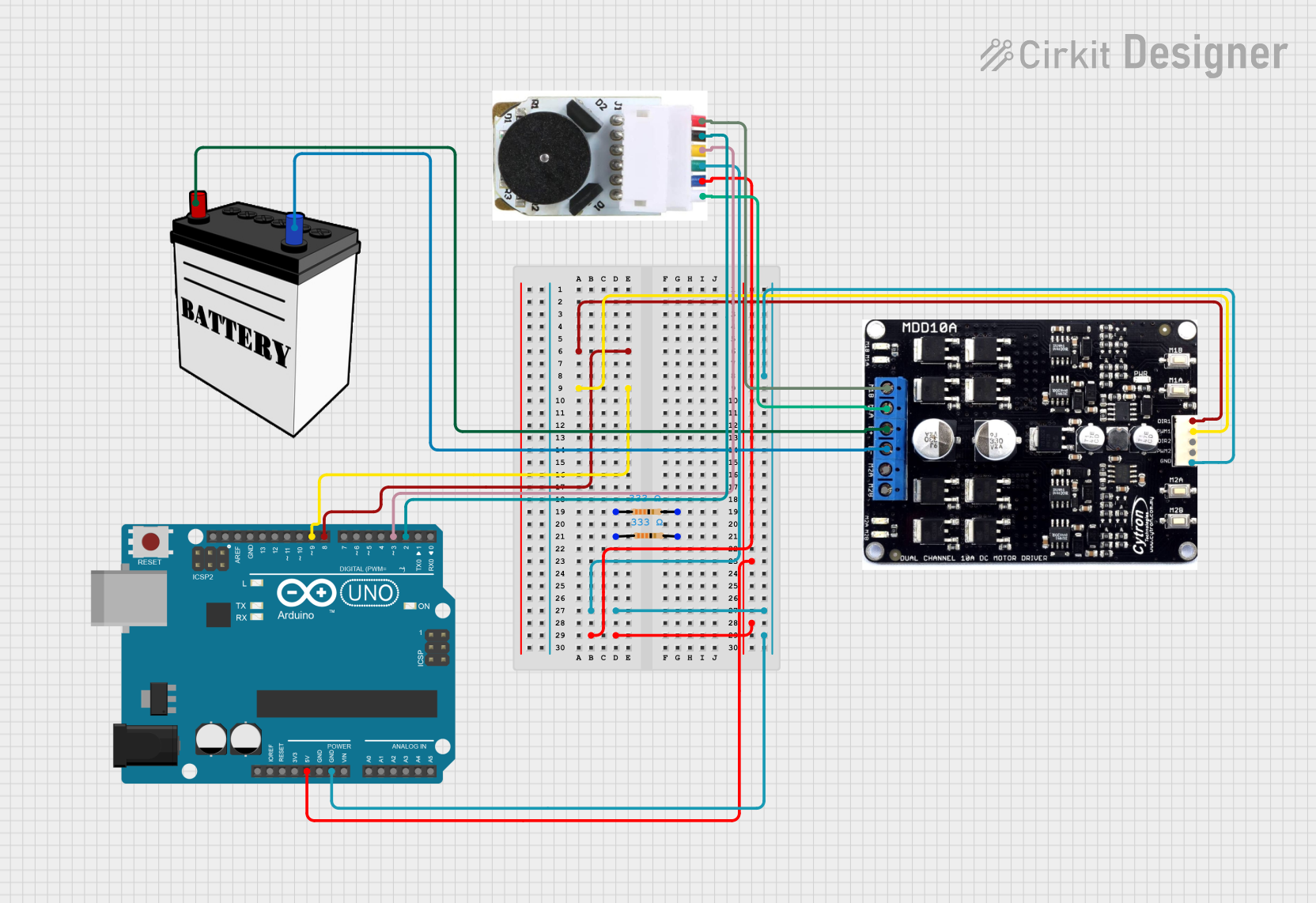
Interfacing with an Arduino UNO

To interface the 12V DC Motor Encoder with an Arduino UNO, follow these steps:

  1. Connect the encoder outputs to two digital pins on the Arduino (e.g., pins 2 and 3).
  2. Connect the motor leads to a motor driver compatible with the Arduino.
  3. Supply the motor driver with 12V DC for motor power.

Sample Arduino Code

// Define the encoder pins
const int encoderPinA = 2;
const int encoderPinB = 3;

// Variables to hold encoder count
volatile long encoderCount = 0;

// Interrupt service routine for encoder A
void encoderISR() {
  if (digitalRead(encoderPinA) == digitalRead(encoderPinB)) {
    encoderCount++;
  } else {
    encoderCount--;
  }
}

void setup() {
  // Set encoder pins as inputs
  pinMode(encoderPinA, INPUT);
  pinMode(encoderPinB, INPUT);
  
  // Attach interrupt for encoder pin A
  attachInterrupt(digitalPinToInterrupt(encoderPinA), encoderISR, CHANGE);
  
  Serial.begin(9600); // Start serial communication at 9600 baud
}

void loop() {
  // Print the encoder count value
  Serial.println(encoderCount);
  delay(1000); // Update every second
}

Note: The above code assumes that the encoder generates interrupts on both rising and falling edges of signal A. Adjust the interrupt type if necessary.

Troubleshooting and FAQs

Common Issues

  • Motor not responding: Ensure that the motor is properly powered and that the encoder is correctly wired to the microcontroller.
  • Inaccurate readings: Check for any loose connections and verify that the encoder's PPR matches the expected value in your code.
  • Noisy signals: Use proper shielding and grounding techniques to minimize electrical noise.

FAQs

Q: Can I use this encoder with a 5V system? A: While the motor requires 12V, the encoder signals can often be read by a 5V system. Check the datasheet to ensure compatibility.

Q: How do I determine the direction of the motor? A: By comparing the phase relationship between Encoder Output A and B, you can determine the direction of rotation.

Q: What is the purpose of the Index pin? A: The Index pin provides a single pulse per revolution, which can be used for more precise control or for establishing a reference position.

Q: How can I increase the accuracy of the encoder? A: Use encoders with a higher PPR value for more precise feedback and ensure that your code correctly handles the encoder signals.

For further assistance, consult the manufacturer's datasheet and technical support resources.