How to Use DC MCB (Red): Examples, Pinouts, and Specs
Introduction
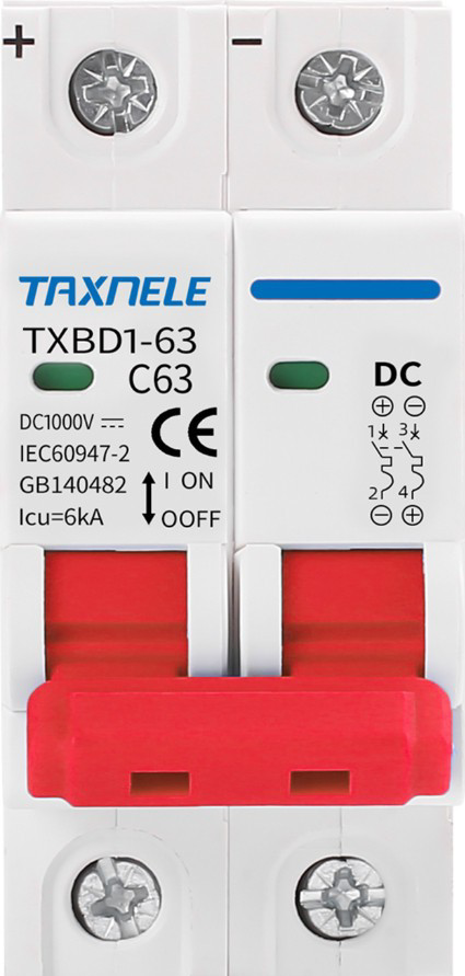
A DC Miniature Circuit Breaker (MCB) is a compact, electromechanical device designed to protect electrical circuits from overloads and short circuits in direct current (DC) applications. The red color of this specific MCB typically indicates a particular current rating or application, making it easy to identify in electrical panels. DC MCBs are widely used in renewable energy systems, battery banks, electric vehicles, and industrial control systems to ensure the safety and reliability of electrical circuits.
Explore Projects Built with DC MCB (Red)


Explore Projects Built with DC MCB (Red)
Common Applications:
- Solar power systems (e.g., photovoltaic arrays)
- Battery storage systems
- Electric vehicle charging stations
- Industrial DC control panels
- Telecommunications equipment
Technical Specifications
Below are the key technical details for the DC MCB (Red):
| Parameter | Value |
|---|---|
| Rated Voltage | 12V DC to 1000V DC |
| Rated Current | Typically 10A, 16A, or 32A (varies by model) |
| Breaking Capacity | 6kA to 10kA |
| Number of Poles | 1P (Single Pole) or 2P (Double Pole) |
| Tripping Curve | Type B, C, or D (varies by application) |
| Operating Temperature | -25°C to +70°C |
| Mounting Type | DIN Rail |
| Housing Material | Flame-retardant thermoplastic |
| Color | Red (indicates specific rating or use) |
Pin Configuration and Descriptions
The DC MCB does not have traditional "pins" but instead features terminal connections for input and output. Below is a description of the terminals:
| Terminal | Description |
|---|---|
| Line (Input) | Connects to the positive terminal of the DC power source. |
| Load (Output) | Connects to the positive terminal of the load. |
| Neutral | Not applicable for single-pole DC MCBs. |
Usage Instructions
How to Use the DC MCB in a Circuit
- Determine the Rating: Select the appropriate DC MCB based on the voltage, current, and tripping curve required for your application.
- Mounting: Install the MCB on a standard DIN rail in your electrical panel.
- Wiring:
- Connect the Line (Input) terminal to the positive terminal of the DC power source.
- Connect the Load (Output) terminal to the positive terminal of the load.
- Ensure all connections are secure and use appropriately rated wires.
- Testing: After installation, test the circuit to ensure the MCB trips under fault conditions (e.g., short circuit or overload).
Important Considerations and Best Practices
- Always ensure the MCB's voltage and current ratings match your circuit requirements.
- Use proper wire gauges to handle the rated current without overheating.
- Avoid using AC MCBs in DC circuits, as they are not designed for DC fault interruption.
- Regularly inspect the MCB for signs of wear, damage, or overheating.
- For high-voltage DC applications, ensure adequate spacing between adjacent MCBs to prevent arcing.
Example: Connecting a DC MCB to an Arduino UNO
While DC MCBs are not directly connected to microcontrollers like the Arduino UNO, they can be used to protect circuits powered by DC sources. Below is an example of how to integrate an MCB into a DC circuit powering an Arduino UNO:
// Example: Arduino UNO circuit protected by a DC MCB
// This setup assumes a 12V DC power source and a 10A DC MCB.

// Circuit Description:
// - The DC MCB is placed between the 12V power source and the Arduino's input.
// - The MCB protects the Arduino and connected components from overloads or short circuits.

void setup() {
  // Initialize the Arduino (no specific code needed for the MCB itself).
  Serial.begin(9600);
  Serial.println("Arduino circuit protected by DC MCB.");
}

void loop() {
  // Example loop to demonstrate normal Arduino operation.
  Serial.println("Circuit running normally...");
  delay(1000);
}

// Note: The DC MCB operates independently of the Arduino and does not require
// any programming. It trips automatically in case of a fault.
Troubleshooting and FAQs
Common Issues and Solutions
| Issue | Possible Cause | Solution |
|---|---|---|
| MCB trips frequently | Overload or short circuit in the circuit | Check the load and wiring for faults. |
| MCB does not trip during a fault | Incorrect rating or faulty MCB | Verify the MCB rating and replace if necessary. |
| Arcing or overheating at terminals | Loose connections or undersized wires | Tighten connections and use proper wire gauge. |
| Difficulty mounting on DIN rail | Incorrect installation technique | Ensure the MCB is aligned properly before snapping onto the rail. |
FAQs
Can I use this DC MCB in an AC circuit?
- No, DC MCBs are specifically designed for direct current applications. Use an AC MCB for alternating current circuits.
What does the red color signify?
- The red color typically indicates a specific current rating or application. Refer to the manufacturer's datasheet for exact details.
How do I reset the MCB after it trips?
- Switch the MCB to the "OFF" position, resolve the fault in the circuit, and then switch it back to the "ON" position.
Can I use a single-pole MCB for a two-wire DC system?
- Yes, but only for the positive line. Ensure the negative line is properly grounded or protected separately if needed.
By following this documentation, you can safely and effectively use the DC MCB (Red) in your electrical circuits.