How to Use DC MCB 10A: Examples, Pinouts, and Specs
Introduction
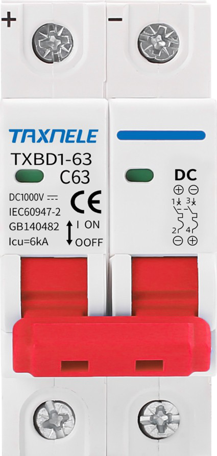
- The DC Miniature Circuit Breaker (MCB) 10A is a protective device designed to safeguard electrical circuits operating on direct current (DC). It is rated for a maximum current of 10 Amperes and is engineered to interrupt the flow of current in the event of an overload or short circuit, preventing damage to connected equipment and reducing fire hazards.
- Common applications include solar power systems, battery banks, electric vehicles, industrial DC circuits, and other low-voltage DC applications requiring reliable circuit protection.
Explore Projects Built with DC MCB 10A


Explore Projects Built with DC MCB 10A
Technical Specifications
- Rated Current (In): 10 Amperes
- Rated Voltage (Ue): Up to 250V DC (varies by model; check datasheet for specifics)
- Breaking Capacity (Icu): Typically 6kA (consult manufacturer for exact value)
- Poles: 1P (single-pole) or 2P (double-pole) configurations available
- Trip Curve: Type C (standard for most DC applications; trips at 5-10 times rated current)
- Operating Temperature Range: -20°C to +70°C
- Mounting: DIN rail compatible
- Standards Compliance: IEC 60947-2 or equivalent
Pin Configuration and Descriptions
The DC MCB 10A typically has screw terminals for input and output connections. Below is a table describing the terminal configuration:
| Terminal Label | Description | Notes |
|---|---|---|
| L+ | Positive DC input terminal | Connect to the positive side of the DC power source. |
| L- | Negative DC input terminal | Connect to the negative side of the DC power source. |
| OUT+ | Positive DC output terminal | Connect to the positive side of the load. |
| OUT- | Negative DC output terminal | Connect to the negative side of the load. |
Note: For single-pole MCBs, only the positive terminals (L+ and OUT+) are used, while the negative side is directly connected.
Usage Instructions
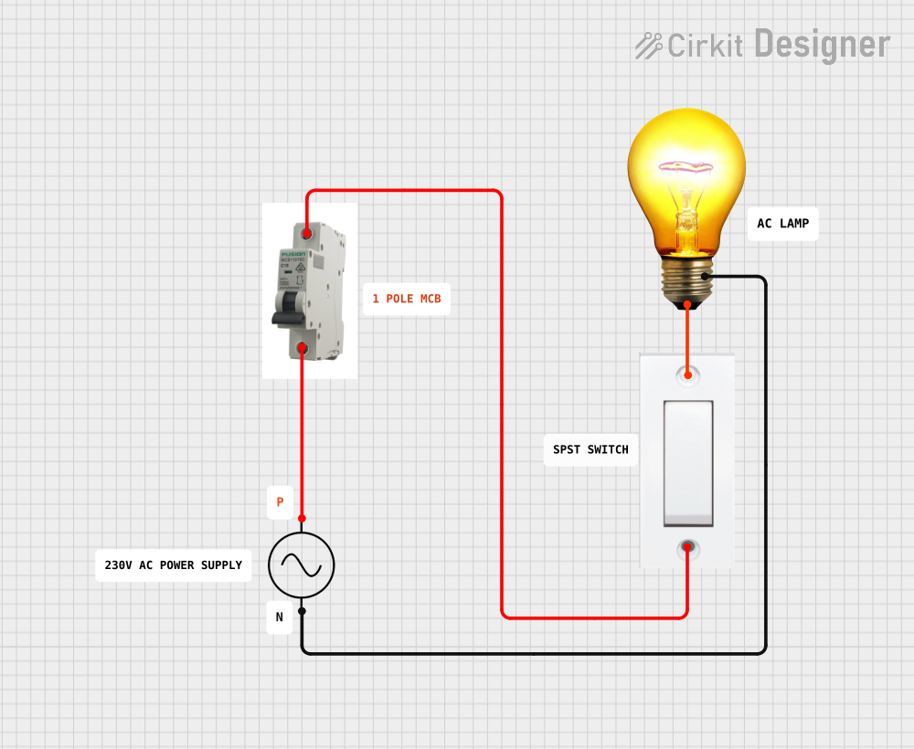
Installation:
- Mount the DC MCB 10A securely on a standard DIN rail in an enclosure or distribution box.
- Ensure the power supply is turned off before making any connections.
- Connect the input terminals (L+ and L-) to the DC power source and the output terminals (OUT+ and OUT-) to the load. Use appropriately rated wires for the current and voltage.
Operation:
- Once installed, switch the MCB to the "ON" position to allow current to flow through the circuit.
- In the event of an overload or short circuit, the MCB will trip to the "OFF" position, interrupting the current flow. Reset the MCB by switching it back to "ON" after resolving the issue.
Important Considerations:
- Ensure the MCB's rated current (10A) matches the requirements of your circuit. Using an underrated or overrated MCB can lead to improper protection.
- Avoid exposing the MCB to excessive heat, moisture, or corrosive environments.
- For circuits with high inrush currents (e.g., motors), verify that the trip curve (Type C) is suitable.
Example Application with Arduino UNO: While the DC MCB 10A is not directly interfaced with microcontrollers like the Arduino UNO, it can be used to protect circuits powered by DC sources connected to the Arduino. For example, in a solar-powered Arduino project, the MCB can safeguard the power supply line.
// Example: Arduino code to monitor a DC circuit's current
// This code assumes a current sensor (e.g., ACS712) is used to measure current.
// The MCB protects the circuit from overloads or short circuits.

const int currentSensorPin = A0; // Analog pin connected to the current sensor
float sensitivity = 0.185;       // Sensitivity of ACS712 (e.g., 185mV/A for 5A model)
float offsetVoltage = 2.5;       // Sensor output at 0A (typically 2.5V for ACS712)
float current;                   // Variable to store measured current

void setup() {
  Serial.begin(9600); // Initialize serial communication
}

void loop() {
  int sensorValue = analogRead(currentSensorPin); // Read sensor value
  float voltage = (sensorValue / 1023.0) * 5.0;   // Convert to voltage (5V reference)
  current = (voltage - offsetVoltage) / sensitivity; // Calculate current in Amperes

  Serial.print("Current: ");
  Serial.print(current);
  Serial.println(" A");

  delay(1000); // Wait 1 second before next reading
}
Note: The MCB in this example is used to protect the DC power source and load. The Arduino monitors the current for additional diagnostics.
Troubleshooting and FAQs
Common Issues
MCB Trips Frequently:
- Cause: Circuit overload or short circuit.
- Solution: Verify the load current does not exceed 10A. Check for short circuits in the wiring or connected devices.
MCB Does Not Trip During Overload:
- Cause: Faulty MCB or incorrect trip curve selection.
- Solution: Replace the MCB if defective. Ensure the trip curve (Type C) is appropriate for the application.
MCB Fails to Reset:
- Cause: Persistent fault in the circuit or damaged MCB.
- Solution: Inspect the circuit for faults and resolve them. Replace the MCB if it is damaged.
FAQs
Q: Can the DC MCB 10A be used in AC circuits?
A: No, this MCB is specifically designed for DC applications. Using it in AC circuits may result in improper operation or damage.Q: How do I select the correct MCB for my circuit?
A: Ensure the MCB's rated current matches the maximum load current of your circuit. Also, consider the trip curve and breaking capacity based on your application.Q: Can I use a single-pole MCB for a two-wire DC system?
A: Yes, but only the positive line will be protected. For full protection, use a double-pole MCB.Q: What happens if the MCB is exposed to high temperatures?
A: High temperatures can affect the MCB's performance and may cause it to trip prematurely. Ensure proper ventilation and avoid installing the MCB near heat sources.
This concludes the documentation for the DC MCB 10A. Always follow safety guidelines and consult the manufacturer's datasheet for detailed specifications.