How to Use troyka-motion-sensor: Examples, Pinouts, and Specs
Introduction
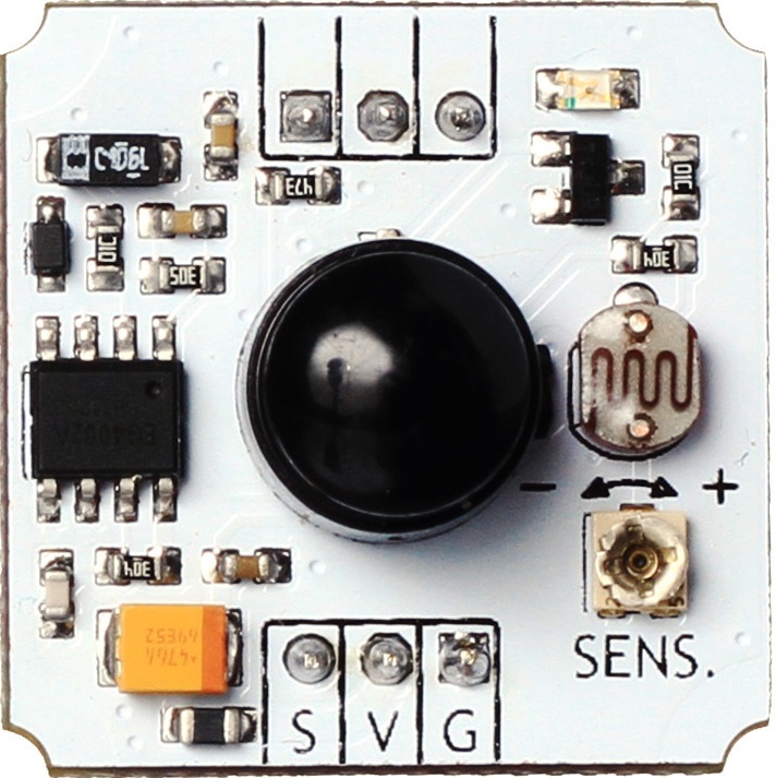
The Troyka Motion Sensor is an electronic device designed to detect motion in its surrounding environment. This sensor is commonly used in applications such as security systems, automatic lighting, and interactive installations. By integrating this sensor into an electronic circuit, users can automate responses based on the detection of movement.
Explore Projects Built with troyka-motion-sensor

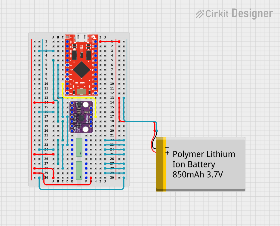
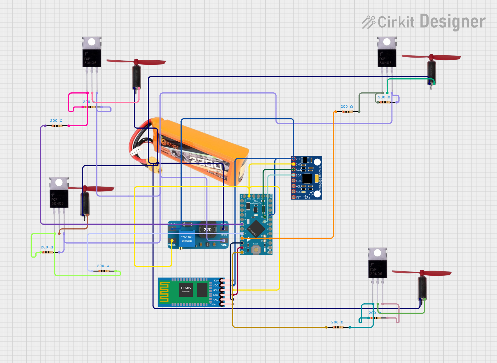
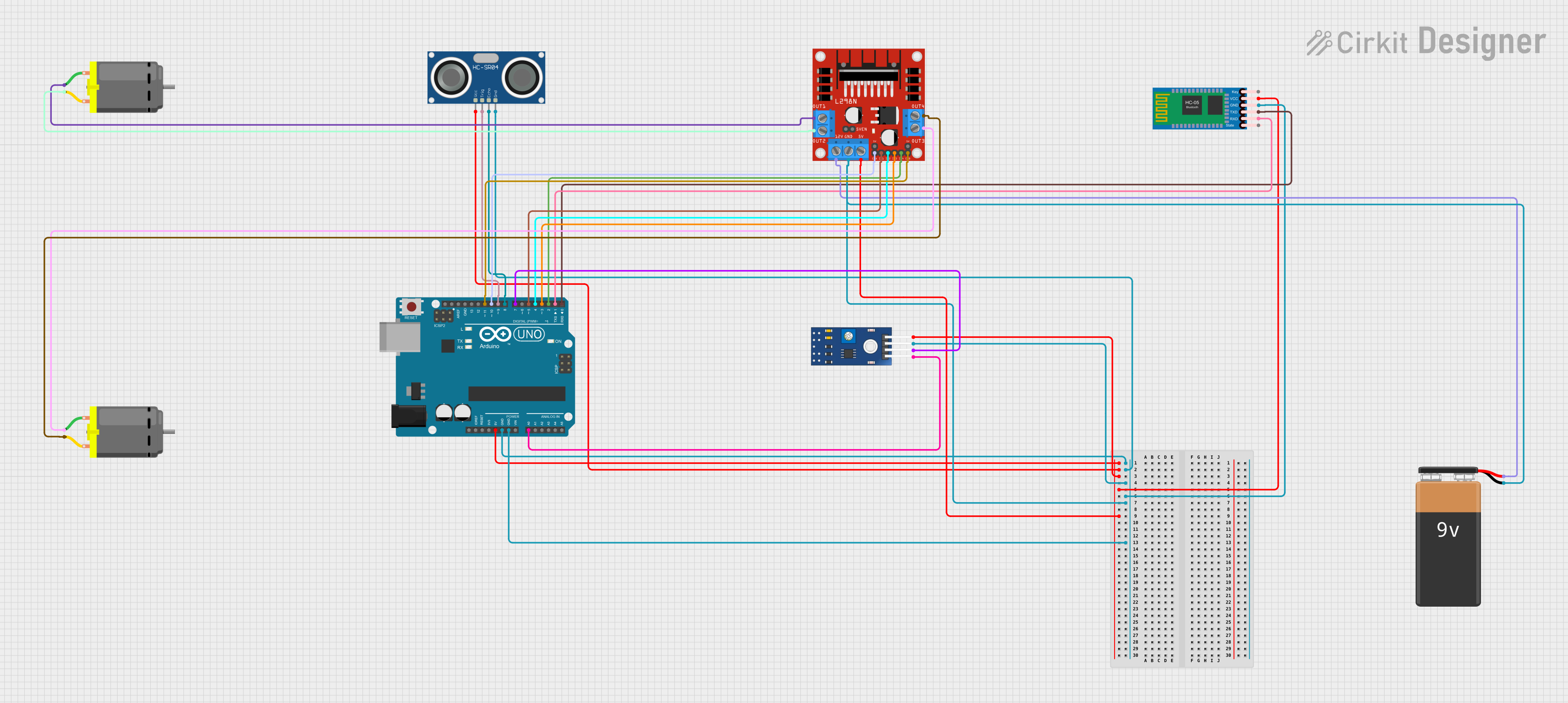
Explore Projects Built with troyka-motion-sensor
Technical Specifications
Key Technical Details
- Operating Voltage: 3.3V to 5V DC
- Current Consumption: Approx. 15 mA
- Detection Angle: Up to 100 degrees
- Detection Distance: Up to 3 meters (adjustable)
- Output Type: Digital (High/Low signal)
- Delay Time: Adjustable (0.3 seconds to 5 minutes)
- Operating Temperature: -20°C to +80°C
Pin Configuration and Descriptions
| Pin Number | Name | Description |
|---|---|---|
| 1 | VCC | Power supply input (3.3V to 5V DC) |
| 2 | OUT | Digital output signal (High/Low) |
| 3 | GND | Ground connection |
Usage Instructions
Connecting to a Circuit
- Connect the VCC pin to a 3.3V or 5V power supply.
- Connect the OUT pin to a digital input pin on a microcontroller, such as an Arduino UNO.
- Connect the GND pin to the ground of the power supply and the microcontroller.
Important Considerations and Best Practices
- Ensure that the power supply voltage matches the operating voltage of the sensor.
- Avoid placing the sensor in an environment with frequent temperature fluctuations, as this may cause false triggers.
- Adjust the delay time and sensitivity as needed for your specific application.
- Use pull-up or pull-down resistors on the output pin if required by your microcontroller.
Example Code for Arduino UNO
// Define the pin connected to the motion sensor's output
const int motionSensorPin = 2;

void setup() {
  // Initialize the motion sensor pin as an input
  pinMode(motionSensorPin, INPUT);
  // Begin serial communication at a baud rate of 9600
  Serial.begin(9600);
}

void loop() {
  // Read the state of the motion sensor
  int sensorValue = digitalRead(motionSensorPin);

  // Check if motion was detected
  if (sensorValue == HIGH) {
    // Motion detected
    Serial.println("Motion detected!");
    // Implement your response to motion detection here
  } else {
    // No motion detected
    Serial.println("No motion detected.");
  }

  // Small delay to avoid overwhelming the serial output
  delay(100);
}
Troubleshooting and FAQs
Common Issues
- Sensor not responding: Ensure that all connections are secure and the power supply is within the specified voltage range.
- False triggers: Adjust the sensitivity and delay time, and check for sources of interference or rapid temperature changes.
- No output signal: Verify that the sensor is correctly powered and the output pin is connected to the microcontroller.
Solutions and Tips for Troubleshooting
- Double-check wiring and solder joints for any loose connections or shorts.
- Test the sensor with a simple LED circuit to confirm it is functioning before connecting to a microcontroller.
- Use a multimeter to check the voltage levels at the VCC and OUT pins.
FAQs
Q: Can the sensor be used outdoors? A: The sensor can be used outdoors but should be protected from direct sunlight and water.
Q: How can I adjust the sensitivity and delay time? A: The sensor typically has onboard potentiometers for adjusting sensitivity and delay time. Rotate these potentiometers to fine-tune the settings.
Q: What is the output signal when motion is detected? A: The output signal goes HIGH (logic level 1) when motion is detected.
Q: Can the sensor differentiate between types of motion? A: No, the sensor only detects the presence of motion, not the type or speed.
Remember to always follow safety guidelines when working with electronic components and consult the sensor's datasheet for detailed information.