Cirkit Designer
Your all-in-one circuit design IDE
Home /
Component Documentation
How to Use LC-Relay-ESP12-2R-D8: Examples, Pinouts, and Specs
Introduction
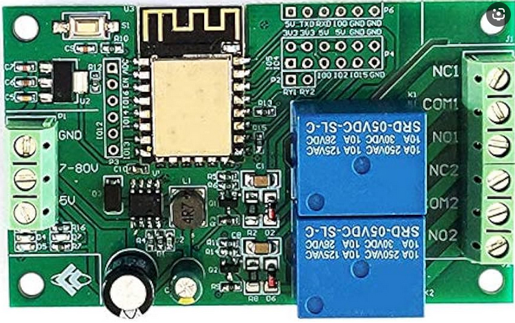
The LC-Relay-ESP12-2R-D8 is a versatile relay module that integrates an ESP12 Wi-Fi module, enabling remote control of two relays via Wi-Fi. This component is ideal for Internet of Things (IoT) applications, allowing users to switch devices on and off remotely. Common use cases include home automation, industrial control systems, and smart appliances.
Explore Projects Built with LC-Relay-ESP12-2R-D8
ESP32-Controlled LoRa and Dual Relay System
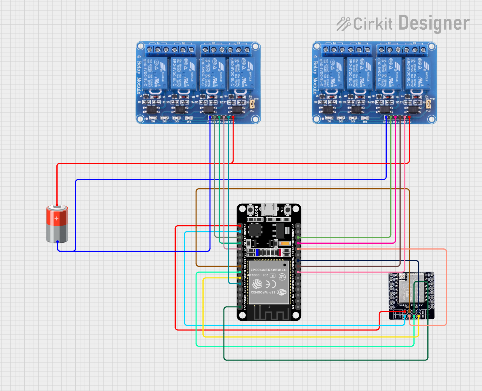
This circuit features an ESP32 microcontroller connected to two 4-channel relay modules and a LORA_RA02 module. The ESP32 uses its GPIO pins to control the relay channels, enabling switching of connected devices, and to communicate with the LORA_RA02 module for wireless data transmission. The relays and the LORA module are powered by a 5v battery, with common ground shared across the components.
ESP32-Powered 8-Channel Relay Controller with Wi-Fi Connectivity

This circuit features an ESP32 microcontroller connected to an 8-channel relay module. The ESP32 controls the relay channels via its GPIO pins, allowing for the switching of external devices or loads through the relays.
ESP32-Powered Wi-Fi Controlled 8-Channel Relay Module

This circuit features an ESP32 microcontroller connected to an 8-channel relay module. The ESP32 controls the relay channels via its GPIO pins, allowing it to switch multiple external devices on and off. The ESP32 also provides power to the relay module.
ESP32 Wi-Fi Controlled Dual Relay Module

This circuit features an ESP32 microcontroller connected to a two-channel 5V relay module. The ESP32 controls the relay channels via its GPIO pins D23 and D22, allowing it to switch external devices on and off. The relay module is powered by the 3.3V and GND pins of the ESP32.
Explore Projects Built with LC-Relay-ESP12-2R-D8
ESP32-Controlled LoRa and Dual Relay System
This circuit features an ESP32 microcontroller connected to two 4-channel relay modules and a LORA_RA02 module. The ESP32 uses its GPIO pins to control the relay channels, enabling switching of connected devices, and to communicate with the LORA_RA02 module for wireless data transmission. The relays and the LORA module are powered by a 5v battery, with common ground shared across the components.
ESP32-Powered 8-Channel Relay Controller with Wi-Fi Connectivity
This circuit features an ESP32 microcontroller connected to an 8-channel relay module. The ESP32 controls the relay channels via its GPIO pins, allowing for the switching of external devices or loads through the relays.
ESP32-Powered Wi-Fi Controlled 8-Channel Relay Module
This circuit features an ESP32 microcontroller connected to an 8-channel relay module. The ESP32 controls the relay channels via its GPIO pins, allowing it to switch multiple external devices on and off. The ESP32 also provides power to the relay module.
ESP32 Wi-Fi Controlled Dual Relay Module
This circuit features an ESP32 microcontroller connected to a two-channel 5V relay module. The ESP32 controls the relay channels via its GPIO pins D23 and D22, allowing it to switch external devices on and off. The relay module is powered by the 3.3V and GND pins of the ESP32.
Technical Specifications
Key Technical Details
| Parameter | Value |
|---|---|
| Operating Voltage | 5V DC |
| Relay Channels | 2 |
| Wi-Fi Module | ESP12 |
| Max Current (Relay) | 10A @ 250V AC / 10A @ 30V DC |
| Power Consumption | < 1W |
| Communication | Wi-Fi (802.11 b/g/n) |
| Dimensions | 50mm x 50mm x 20mm |
Pin Configuration and Descriptions
Relay Module Pins
| Pin Number | Pin Name | Description |
|---|---|---|
| 1 | VCC | Power supply (5V) |
| 2 | GND | Ground |
| 3 | IN1 | Control signal for Relay 1 |
| 4 | IN2 | Control signal for Relay 2 |
| 5 | TX | UART Transmit (ESP12) |
| 6 | RX | UART Receive (ESP12) |
| 7 | CH_PD | Chip Power-Down (ESP12) |
| 8 | RST | Reset (ESP12) |
Relay Output Terminals
| Terminal | Description |
|---|---|
| NO1 | Normally Open contact for Relay 1 |
| COM1 | Common contact for Relay 1 |
| NC1 | Normally Closed contact for Relay 1 |
| NO2 | Normally Open contact for Relay 2 |
| COM2 | Common contact for Relay 2 |
| NC2 | Normally Closed contact for Relay 2 |
Usage Instructions
How to Use the Component in a Circuit
- Power Supply: Connect the VCC pin to a 5V power supply and the GND pin to the ground.
- Control Signals: Connect IN1 and IN2 to the digital output pins of a microcontroller (e.g., Arduino UNO) to control the relays.
- Wi-Fi Configuration: Use the TX and RX pins to communicate with the ESP12 module for Wi-Fi configuration.
- Relay Outputs: Connect the devices you want to control to the relay output terminals (NO, COM, NC).
Important Considerations and Best Practices
- Ensure the power supply is stable and within the specified voltage range.
- Use appropriate flyback diodes across relay coils to protect against voltage spikes.
- Avoid exceeding the maximum current and voltage ratings of the relays.
- Securely mount the module to prevent short circuits and mechanical damage.
Example Arduino Code
#include <ESP8266WiFi.h>

// Define relay control pins
const int relay1Pin = D1; // GPIO5
const int relay2Pin = D2; // GPIO4

// Wi-Fi credentials
const char* ssid = "your_SSID";
const char* password = "your_PASSWORD";

void setup() {
  // Initialize serial communication
  Serial.begin(115200);

  // Initialize relay control pins as outputs
  pinMode(relay1Pin, OUTPUT);
  pinMode(relay2Pin, OUTPUT);

  // Connect to Wi-Fi
  WiFi.begin(ssid, password);
  while (WiFi.status() != WL_CONNECTED) {
    delay(1000);
    Serial.println("Connecting to WiFi...");
  }
  Serial.println("Connected to WiFi");

  // Turn off relays initially
  digitalWrite(relay1Pin, LOW);
  digitalWrite(relay2Pin, LOW);
}

void loop() {
  // Example: Toggle relays every 5 seconds
  digitalWrite(relay1Pin, HIGH); // Turn on Relay 1
  delay(5000);                   // Wait for 5 seconds
  digitalWrite(relay1Pin, LOW);  // Turn off Relay 1

  digitalWrite(relay2Pin, HIGH); // Turn on Relay 2
  delay(5000);                   // Wait for 5 seconds
  digitalWrite(relay2Pin, LOW);  // Turn off Relay 2
}
Troubleshooting and FAQs
Common Issues Users Might Face
Wi-Fi Connection Problems:
- Ensure the SSID and password are correct.
- Check if the Wi-Fi signal is strong enough.
Relays Not Switching:
- Verify the control signals (IN1 and IN2) are correctly connected.
- Ensure the power supply is adequate.
Module Not Powering On:
- Check the VCC and GND connections.
- Ensure the power supply provides sufficient current.
Solutions and Tips for Troubleshooting
- Wi-Fi Connection: Use a Wi-Fi analyzer app to check signal strength and interference.
- Control Signals: Use a multimeter to verify the voltage levels on IN1 and IN2.
- Power Supply: Use a regulated power supply to avoid voltage fluctuations.
By following this documentation, users can effectively integrate and utilize the LC-Relay-ESP12-2R-D8 in their IoT projects, ensuring reliable and efficient remote control of devices.