
How to Use DC-DC Buck LM2596 3A LED: Examples, Pinouts, and Specs
 Design with DC-DC Buck LM2596 3A LED in Cirkit Designer
Introduction
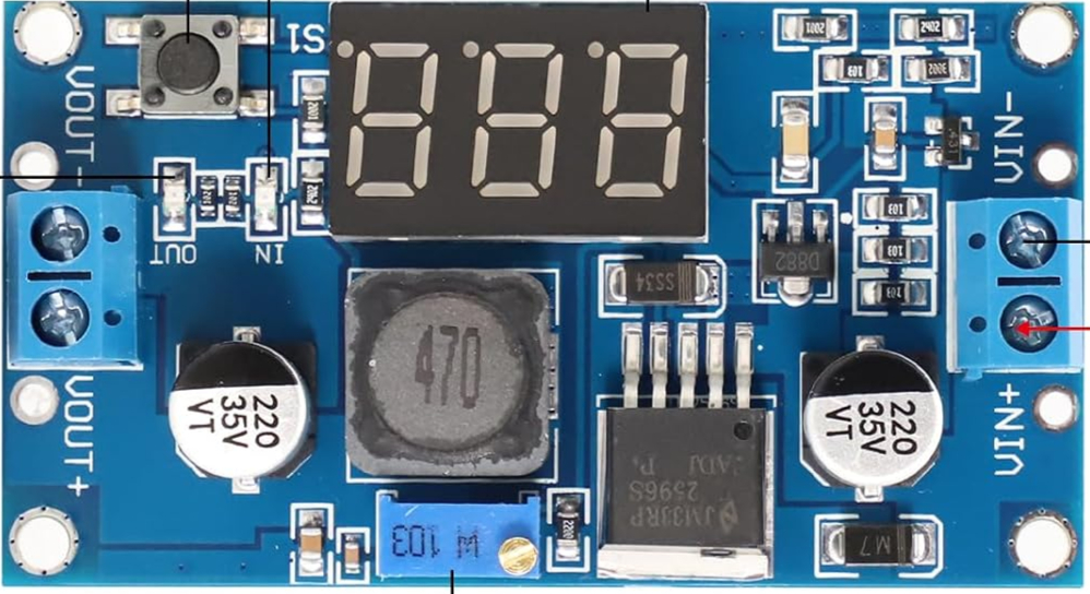
The DC-DC Buck LM2596 3A LED module is a step-down voltage regulator designed to efficiently convert a higher input voltage to a lower output voltage. It is based on the LM2596 chip, which is known for its high efficiency and reliability. This module is equipped with an onboard LED display that shows the output voltage, making it convenient for real-time monitoring.
Common applications include:
- Powering low-voltage devices from higher-voltage sources (e.g., 12V to 5V conversion).
- Battery-powered systems where efficient voltage regulation is critical.
- DIY electronics projects requiring adjustable voltage outputs.
- Arduino and microcontroller-based projects.
Explore Projects Built with DC-DC Buck LM2596 3A LED
 Open Project in Cirkit Designer
 Open Project in Cirkit Designer
 Open Project in Cirkit Designer
 Open Project in Cirkit Designer
Explore Projects Built with DC-DC Buck LM2596 3A LED
Open Project in Cirkit DesignerOpen Project in Cirkit DesignerOpen Project in Cirkit DesignerOpen Project in Cirkit DesignerTechnical Specifications
- Input Voltage Range: 4V to 40V DC
- Output Voltage Range: 1.25V to 37V DC (adjustable via potentiometer)
- Maximum Output Current: 3A (with proper heat dissipation)
- Efficiency: Up to 92% (depending on input/output voltage difference)
- Output Voltage Display: 3-digit 7-segment LED display
- Switching Frequency: 150 kHz
- Operating Temperature: -40°C to +85°C
- Dimensions: Approximately 50mm x 26mm x 14mm
Pin Configuration and Descriptions
| Pin Name | Description |
|---|---|
VIN+ |
Positive input voltage terminal (connect to the higher voltage source). |
VIN- |
Negative input voltage terminal (connect to ground of the power source). |
VOUT+ |
Positive output voltage terminal (connect to the load). |
VOUT- |
Negative output voltage terminal (connect to the ground of the load). |
Potentiometer |
Adjustable knob to set the desired output voltage. |
Usage Instructions
How to Use the Component in a Circuit
Connect the Input Voltage:
- Connect the positive terminal of your power source to
VIN+. - Connect the ground terminal of your power source to
VIN-. - Ensure the input voltage is within the range of 4V to 40V DC.
- Connect the positive terminal of your power source to
Connect the Output Load:
- Connect the positive terminal of your load to
VOUT+. - Connect the ground terminal of your load to
VOUT-.
- Connect the positive terminal of your load to
Adjust the Output Voltage:
- Use the onboard potentiometer to adjust the output voltage.
- Turn the potentiometer clockwise to increase the voltage and counterclockwise to decrease it.
- Monitor the output voltage on the LED display.
Verify Connections:
- Double-check all connections before powering the module to avoid damage.
Important Considerations and Best Practices
- Heat Dissipation: If the module is used at high currents (close to 3A), ensure proper heat dissipation by attaching a heatsink to the LM2596 chip.
- Voltage Difference: For optimal efficiency, keep the input voltage at least 2V higher than the desired output voltage.
- Polarity: Ensure correct polarity when connecting the input and output terminals. Reversing polarity can damage the module.
- Load Testing: Before connecting sensitive devices, test the output voltage with a multimeter to ensure it matches the desired value.
Example: Using with Arduino UNO
The LM2596 module can be used to power an Arduino UNO from a 12V source by stepping down the voltage to 5V. Below is an example code to read an analog sensor powered by the LM2596 module:
// Example code for Arduino UNO to read an analog sensor
// Ensure the LM2596 module is set to output 5V before connecting to Arduino

const int sensorPin = A0; // Analog pin connected to the sensor
int sensorValue = 0;      // Variable to store the sensor reading

void setup() {
  Serial.begin(9600); // Initialize serial communication at 9600 baud
  pinMode(sensorPin, INPUT); // Set the sensor pin as input
}

void loop() {
  sensorValue = analogRead(sensorPin); // Read the sensor value
  Serial.print("Sensor Value: ");
  Serial.println(sensorValue); // Print the sensor value to the Serial Monitor
  delay(500); // Wait for 500ms before the next reading
}
Troubleshooting and FAQs
Common Issues and Solutions
No Output Voltage:
- Cause: Incorrect wiring or polarity.
- Solution: Verify all connections and ensure correct polarity for both input and output terminals.
Output Voltage Not Adjustable:
- Cause: Faulty potentiometer or insufficient input voltage.
- Solution: Check the input voltage and ensure it is at least 2V higher than the desired output. If the potentiometer is damaged, replace the module.
Overheating:
- Cause: High current draw without proper heat dissipation.
- Solution: Attach a heatsink to the LM2596 chip and ensure adequate ventilation.
LED Display Not Working:
- Cause: Faulty module or insufficient input voltage.
- Solution: Verify the input voltage and check for any visible damage to the module.
FAQs
Can the LM2596 module be used with AC input? No, the module only supports DC input. Use a rectifier circuit to convert AC to DC before connecting.
What is the maximum power output of the module? The maximum power output is approximately 37W (e.g., 12V at 3A), but this depends on proper heat dissipation.
Can I use this module to charge batteries? Yes, but ensure the output voltage is set to match the battery's charging requirements, and use additional circuitry for safe charging.
Is the module safe for sensitive electronics? Yes, but always verify the output voltage with a multimeter before connecting sensitive devices.